Electro Tech is an online community (with over 170,000 members) who enjoy talking about and building electronic circuits, projects and gadgets. To participate you need to register. Registration is free. Click here to register now.
Welcome to our site! Electro Tech is an online community (with over 170,000 members) who enjoy talking about and building electronic circuits, projects and gadgets. To participate you need to register. Registration is free. Click here to register now.
I am pretty sure that I simulated in TINA but ??
will post. if I had your Email I could just send you the file (I might have it already??)
trying to get several things done but getting no where.
Don't worry, I never though it was a waste of time. I thought you had decided on the NMRA unit anyway. The site I checked tho' didnt have an unpluggable semiconductor. Indeed the thing had components and jumpers straddling it making removal/replacement almost impossible. The PC board is of poor quality making resoldering a total mess. The foils just peel off. I suggest you use the circuit by all means but make your own boards.
Soldering.
MrDeb's method is valid too. The whole idea is to get liquid solder to flow between the copper foil, the component lead and the soldering iron tip as quickly as possible. To improve your skills I suggest an excersize. Take some old component trimmings and cut 12 one half inch lengths of wire. Now using a brand new 30 watt fine tipped iron make a half inch cube. When you have finished you will have learned some brand new words that most dictionaries will not print, your soldering skills will have improved dramatically and don't worry the blisters will heal nicely. By the way, when you described your soldering iron I started to cry. I don't know if its too late but try replacing the tip with a fine tipped copper core steel "plated" one. That might work for you.
MrDeb,
You are right about the MTBF being less for devices that use a lot of components. But that is assuming that each component has the same unit MTBF. The multivibrator (flasher) has about ten components but all but two have a unit MTBF that is in orbit and can be discounted. That leaves the two transistors. I have found that discrete components seem to be more rugged when it comes to voltage spikes and unruly power variations than a chip. When I was working we had these very large PC boards (15x10 inches) There were about 200 DIP chips on each board. Every chip had its own noise reducing capacitor connected between pin 1 and 14 (Vcc and ground) even though the designers used all kinds of noise reducing technology to keep the supplies at exactly 5 volts. So I don't know how an op amp will tollerate back EMF pulses from an engine motor or variations in the output of its power supply. Perhaps it has its own internal voltage regulation. I really don't know. The whole argument is really about a coin toss.
I do like your comment about tubes though. My God that was a long time ago but I got my electronic education in tubes. Wanna talk pentodes? Yet my dear brother in law got a job with a company that manufactured very expensive audio amplifiers that actually used tubes. Er Um in the 80s?? Well the theory went that tubes had a very linear amplification curve and provided very very Hi Fi. The tubes however, were imported from Russia. The question arose " Why were the Russians still making tubes?". The answer ---Defense. During the later years of friendship between The Soviet Union and China a chinese pilot flew a Russian Mig across the straight to Taiwan. Naturally the intelligence agencies took it appart and found that the avionics were "old fashioned" and actually used tubes. The design was not stupid. The tubes could withstand the magnetic impulse generated by a nuclear explosion. Transistors would have fried. The US have a testing jetty somewhere in Calif which is constructed of only wood (no metal nails). They stick an F16 on the end of it and expose it to magnetic impulses to test the shielding. Very expensive. The Russians just used tubes. I have to admire elegance.
as I understand it.
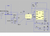
Here is a pic of the NMRA circuit. VERY simple for sure. And it actually works in LT Spice.
Got a basic circuit in TINA working as well but no 555 or other componetsetc.
Nice circuit. Opto isolator driven by the voltage drop across a bridge rectifier is a nice touch. I think one loses about 1.4 volts across track power but for DCC that is moot. Isn't the NE555 a timer though? That would mean the signals go from green to red and stay that way depending on a time lapse rather than the ocupancy of the track. Or do the signals stay red until a preset time period after the opto isolator goes inactive (track clear)?
Just checked out the sites for the comercial stuff you sent me. Ouch! That is why I built my own too. By the way Lenz is in Euro land. I don't know if you noticed but the pound and dollar are in the tank. This means the stuff made in Britain and the US should be cheaper. In your dreams I guess.
By the way Lenz is in Euro land. I don't know if you noticed but the pound and dollar are in the tank. This means the stuff made in Britain and the US should be cheaper.
Now you just made me fall off my chair laughing. Britain doesn't make anything anymore, the unions priced companies out of the market by wanting more and more money, so the companies moved production to asia and the like.
I already did many price comparison and home made alternate solution searches. It may take a while to etch, solder and test each circuit but this is definately the best route
as I understand it.
Here is a pic of the NMRA circuit. VERY simple for sure. And it actually works in LT Spice.
Got a basic circuit in TINA working as well but no 555 or other componetsetc.
I see where the AC enters from V1+ to track then thru R4 and connects to the bridge between D5 and D6. I also see it returning to V1- from between D4 and D7.
Surely this means current is always flowing thru U2 when a loco is present therefore the NPN in U2 is always on when a loco is present but not when no loco is there. This begs the question why is a bridge required? Why not just put an AC optocoupler in line and when a loco is there it switches on?
the circuit I posted from LT SPICE is the same circuit from the NMRA site.
LT Spice dosn't have the ac optocoupler. but it really shouldn't matter in a simulation.
as for the 555 in the circuit. believe the artical mentoned that its to prevent flickering of circuit. Easy Block Detection and 2-Color Signals, Part 1: Detection Systems and Circuits
The detector part looks a bit confusing to me too. I thought the bridge was used to form a constant voltage to drive the isolator. But taking a closer look I find its a simple bridge rectifier. There is always current flowing through the 10K and 33 ohm resistor via the bridge and the Opto isolator. I guess when an engine comes along it shorts the 10K resistor allowing a higher current to flow through the circuit and "illuminating" the IR LED. I guess an AC isolator would work too, but I'm thinking that the DCC alternating voltage adding and subtracting from the opto isolators AC might have something to do with it. What you don't need is a set of 100 cycle pulses leaving the isolator and being fed to the NE555. I'm missing something here.
Detector/signal driver costs.
Ah yes, the real world of business. The US is in the same boat. Everything is now made in China. Actually it isn't "made" there it is only assembled there. Even the Chinese get components from elsewhere. The nub is the middle man. He makes the millions. For eight blocks of signalling though it works out at $15 dollars block. Then there is the signal(s) and the power supplies. My question. Just who can afford to buy this stuff. I mean I have an income and when I was working I did OK. But even if I had the money I don't think I would have blown that on my hobby. I would have rather bought my daughter a new wardrobe.
The mags are pushing products like this too. And they have the gall to call it a great hobby. Researching the prototype, gathering the materials, setting up a production method and actually doing it is the hobby. Buying stuff and plugging it onto the layout is just Buying?!? I guess. I have used textile dyes for coloring, chopped up sponges for ground cover, made rock face molds from silicon caulking and plaster of paris and yes, signals from photos, diagrams and etched brass. I have even put instructions for making signals on the net. (I need to work on that some more though). Go to "sites.google.com/site/modeltrainsignals". The signals are US type but if someone in the UK gets some specs from BR and draws up an etching mask I feel sure that it would work.
I used to live in Rainham Kent and I would be interested in making the South East rail signal with the four aspects plus a feather indicating the branch to the Isle of Sheppey that is still working at the local railway station.
As an aside here. I use an old ROCO DCC system. I cannot program my engines. There is a company in the US called MRC that makes DCC throttles and systems. Their units have all kinds of bells and whistles including programming facilities. Now I live in Slovakia. I use 230 volts AC. MRC in the US uses 110. I can buy a US MRC Prodigy Advance for $200. I would have to buy a transformer though. "Never fear" I told myself. "Self" I said, "there is a company in the UK called GAUGEMASTER that has the 230 volt version. I will purchase the unit from them". I think they charge 275 POUNDS! And the unit didn't have all the features of the US model.
Tell me what you think of my signals. By the way Can I put JPEG files on this forum.
I'm doing something wrong here. I go to your link and I get the NMRA site. The circuit they discuss uses a shorted bridge rectifier in series with track power. This provides a constant 1.4 volts across the bridge. The circuit takes that 1.4 volts and uses it to feed the Opto-isolator. Am I looking at a wrong page?
I have gone through my stuff here and came up with a question for you. I looked at the revised circuit board MrDeb drew up for you and was wondering how you get the etching pattern onto your copper clad PC board? If you are using a pen and you say you need 26 detectors you will be tied up for years hand drawing each one. I use a neat system that works great. It's called "Press-n-Peel. The company that produces the film is on the net "www.techniks.com". They have a branch in the UK. The system works as follows.
1/ Print a mirror image of your PC design on plain paper. Fill a 8½ x 11 inch page with as many imagese as you can.
2/ Now using a laser copier copy the paper image onto the film. Most copiers have a single sheet feed slot.
3/ Cut a single (square) image out of the set with a razor knife and tape it at the edges upside down onto a perfectly cleaned copper clad board. Now you know why it has to be a mirror image.
4/ Set an iron (for ironing your shirts) to between 275 -375 degrees F. This setting is for "acrylic" and "polyester".
5/ Cover the PC board and film with a paper towel (dry - It cannot be damp) and with a little pressure apply the iron for about 2½ to 4 minutes. (please do not use steam)
6/ While still warm gently remove the tape and then flush the film away with cold running water. The board is now ready for etching.
You can also make repairs at this stage with your pen
This would be a great way for making MrDeb's modified board. One sheet can provide you with about ten 2x4 inch boards.
P.S. I have no idea what a pack f 5 sheets cost in the UK. I just hope you don't fall off the chair again.
the schematic is way at the bottom.
The 10k resistor is simulating the 10k resistor mounted on each set of wheels (one per car).
basically its a full wave bridge rectifier that feeds the opto coupler.
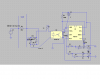
I was looking at this one (see attachment) but now you've shown the bridge in diode form it doesn't make sense. The AC squarewave flows when a loco is on the block. One rail is uninterupted and the other is divided into sections (blocks).
I think this is where I got confused. I thought this circuit detected a fall in current, not that current was present. So in theory, if this senses current, i.e. when a loco connects the two rails and current flows, this is when the opto isolator fires up switching the npn and thus switching my signalling circuit.
But as they've drawn it it's taking all current restricted by the resistor so is this going to leave enough for the loco?
That's the diagram at the NMRA site. The full wave rectifier's only function is to provide two diodes in series with AC power One set of two for the positive cycle and one set for the negative. Note the shorting jumper at the + and - output. A silicon PN jumction always drops 0.7 volts no matter what the current. So if the 16 volt DCC current is 1.6 Ma through a 10K resistor the two diodes will drop 1.4 volts. However the 2Ma may not be enough to light the opto isolators LED. If the Opto unit requires the standard current to light the IR transmitter then I think the maximum resistance across the track should be closer to 1K. But anyway, the 1.4 volts stays constant even when the DCC current is 2Amps. This is what the Twin-T uses across the detector transistor junctions, except it uses two back to back power diodes which drop only 0.7 volts.
Now my DCC unit can deliver two amps before the safety breaker trips. If I change to a four amp unit I have to replace these diodes with four amp ones OR forget about diodes and use four amp power transistors. On the NMRA circuit, what happens during a derailment. Does the bridge rectifier fry before the breaker cut off power. I hope so.
I think I found the problem with the NMRA diag you put up. There is a jumper missing. There should be a wire jumper between the junctions of D4 - D7 and D4 - D5. Could you try that on your simulator program and see what happens?
Well, according to the NMRA diagram the + and - terminals of the bridge are connected together. This means that there are 4 diodes connected in pairs back to back and in series with 16 volts DCC ac power. The bridge is nothing but a low cost 1.4 volt regulator. That jumper in the bridge lets the bulk of the engine motor current through the bridge diodes and not the 33 ohms +opto-isolator. If I got this all wrong then that 33 ohm resistor in series with the Opt-isolator would limit the engine motor current to ½ Amp. Also that resistor is not alone in that circuit. The opto-isolator also has to pass that ½ Amp. I'm not getting something here.
Can you replace the 10K resistor across the track with a ¾ Amp load. A motor or a 25 ohm 15 Watt resistor should do it. Then crank this configuration through your simulation software and see what happens? I am really curious now.
Took a look at DigiKey's specs on the NEC 2506 Opto isolator. Came up with the (disappointing) attached sheet. As given in the NMRA circuit the detctor is not so sensitive. A single car has to provide a resistance of 1.6 Kohms across the track because that is the very minimum current required to trigger the isolator. A fifty car train would add ½ an Amp to the load. That is almost as much as another engine. There is another problem with a single car scenario. If a 1.6Kohm resistor is strapped across one axle and a single set of wheel contacts with the track this would be fine providing the wheel contacts are squeaky clean. So, I hear you cry, why not put resistors across all the axles. They must all be 1.6 Kohms then because if one or more wheel contacts open up on that single car a higher value of resistance is formed and the isolator trips out. A good compromise is to put resistors on half the axles. That is OK until you realise that with a 50 car train that puts an extra Ampere load on your booster.
So if Angie arranges to operate a short line with trains of about ten cars max, this device would probably be OK.
I'm probably on thin ice here, I sell a similar circuit already built...
Go to www.modelRRsignals.com, scroll down the page until you find the circuit. The symbolic logic is there as well as the circuit diagram. No detection circuit, mine is proprietary. The circuit signals both directions and interconnection is shown. Everything is referenced to ground because I have other circuits that can interact.
I tried to follow your circuit as posted but not being familiar with the format and didn't do a redraw. The logic on my board is fairly common. The symbolic drawing should make the logic obvious. Luck with it.......
This site uses cookies to help personalise content, tailor your experience and to keep you logged in if you register.
By continuing to use this site, you are consenting to our use of cookies.

")