Continue to Site

Welcome to our site!

Electro Tech is an online community (with over 170,000 members) who enjoy talking about and building electronic circuits, projects and gadgets. To participate you need to register. Registration is free. Click here to register now.

  • Welcome to our site! Electro Tech is an online community (with over 170,000 members) who enjoy talking about and building electronic circuits, projects and gadgets. To participate you need to register. Registration is free. Click here to register now.

3 aspect model RR signalling help plse

Status
Not open for further replies.
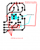
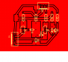
reason for 45s instead of 90s is when you etch the board, the etching solution can hang up in the corners. plus you have less chance of broken traces.
My offer odf sending the transfer paper still stands. then you can iron it on and etch it. lots easier than drawing the traces.
Its really no bother. remember stubbornness can be a good trait but can also lead to failure or disappointment. You run the risk of learning a better process to etch circuit boards.
 
some recommender fixes on your design

pretty good design, just needs some tweeking
see attachement.
the less copper you remove the less etchant you need.
try and stay away from 2 oz boards (more for thinner traces) as the etchant can undercut the copper.
 

Attachments

  • board recommendations.PNG
    board recommendations.PNG
    60.2 KB · Views: 191
Hi Pete, Yes I can view the doc. Thanks for the insight but....

Correct me if I'm wrong but it looks like you're using a relay to each grn, ylw and red.

How are they linked to the detect circuit and further blocks to allow automatic synchronisation and what are you using for block detection? That's the next bit of this project so would be interesting to know.

For a subminiature 1A relay I'd pay £2.88, yet for two 2N3904 transistors which are performing the same function, a switch, I pay £0.098 pence. Please correct me if I'm wrong?

One unit of my current design is 74 pence which includes one 3 way screw connector and two 2 way screw connectors. Also I will be able to connect the detect out to the seep point motor so as to change the signal when the turnout is against the loco.
 
revised board

with filled planes to cut down on etchant and time to etch.
 

Attachments

  • filled pc board.PNG
    filled pc board.PNG
    33.9 KB · Views: 188
I'm new to this forum and have not figured out how to attach a Microsoft Word file to ta posting.
Please avoid diagrams in Microsoft Word. Some of us can't or won't (vbasic scripting risks?) open them.
 
GO get um angi
as for block detection, I thought you were going with IR detectors across the track?
another idea is have the IR emitter next to the detector in between ties. Then place a small mirror (plastic mirror ) under the loco and one under the caboose. then using a latch circuit to turn the detect on (loco detect) then turn off (caboose detect).
this would be pretty easy. the mirrors could be pretty small and ambient light wouldn't be a problem if the IR emitter was pulsed (fairly simple).
let me see what I can come up with.
 
angie

Hi Mr Deb,

No there is only one relay per detector driver board. The output from one relay is connected to the four adjacent block detector driver boards. i.e Two ahead east bound and two ahead westbound. For setting the red against a switch point I fake an occupancy so that the correct aspects are propogated behind a stopped train. The signal in front of the train has to show approach medium divert i.e. flashing yellow. As to the cost of a relay, I have yet to pay more than a dollar for one. The ones I use I bought at an electronic surplus store. The cost is about 90 cents for a SPST type. I agree transistors are cheap but in the envirnment that they are being used i.e. electrical noise, electro mechanical interfacing, the extra components reqired to protect them brought the cost over and above the simple relay. Also my 25 year old ´little´ home project was meant to be just that and anyone was to be able to build, configure, maintain and trouble shoot it without having a degree in electronics. I tried an emitter follower circuit instead of a relay only to find that a transistor failure propogated its condition not only to its neighboring controlers but to its own detector. It was a mess. The relay offers TOTAL isolation and any problem is easilz isolated to a board. The board can easily be unpluged and replaced within seconds. AND, since I adopted this philosphy I have yet to have a failure on my layouts.
Today a self builder can build a PC board for about ten dollars. The two signals run about 9 dollars each. There is of course a one time overhead but even that can be made from materials on hand. One would require a power supply and a home made card rack. I use an old throttle to run my system and the rack is made of timber. One card slot in the rack is reserved for conditioning the power. I use a commercial voltage regulator. The cost of that item was 20 cents.

The detector I use is a Twin T type. It was invented by Lynn Westcot in the 50s. It is a bidirectional current sensor which in its simplest form drives a lamp or relay. It requires two transistors and two resistors. (I seem to remember , I am not at home right now, hence the choppy grammar. I am using a cyrilic keyboard). The cost of these components, which by the way, includes the reed relay is about 3 dollars 50 cents. I also added an inverter and debouncer circuit to prevent chatter. The detector does not require power to be applied to the track to work. So if you are working with DC and a section without power has an engine or car with conductive paint one some axles the detector will still do its job and trigger its relay. I suggest you check on the net. If you cant find anything Ill put something together for you.

Looking forward to this

Pete
 
as for block detection, I thought you were going with IR detectors across the track?

IR is only at point of the IR. The opto isolator version does the whole block, as prototypical. Each wagon/carriage has a resistor across one axle to draw a small level of current so when wagons are left in a block with no loco it still shows the block as being occupied, and thus the previous light shows red.

A block could be as short as 14 inches or as long as 4 feet and the loco or wagon could be anywhere on that block so the previous signal should be red. If the loco is in block 1 and the wagons cover blocks 2 and 3 then blocks 2,3 and 4 should show red.

Hope this makes sense, I read through twice. :)
 
**broken link removed**
this IR idea is perhaps your easiest way to detect a train. a latch is not needed (my bo bo)

LOL, one for each loco and wagon !!!! And then there's the fitting of them, not too much space in N gauge locos you know ;)
 
Its me again.

Can we talk about track occupancy detection.

I have visited a few club layouts and discovered a myriad of devices that detect the presence of trains on a given section of track.

IR devices are OK for trains that are guarranteed to move. Little mirrors on the bottom of the engine work fine. But what happens if the engine uncouples the cars and leaves them standing before leaving? OOps. the track is occupied but the system has just cleared the block. Keeping the transmitter and receiver clean can be a pain too. Disguising them on a layout requires some creativity as well. My conclusion? OK for exhibition layouts where trains just go round and round. For operation? Hm Not so good.

Lasers work a bit better. The beam is shot along all of the track so that anything on it is detected. Mirrors are used to send the beam around the bend. Nice actually, but a bit expensive.

Low impedance relay coils in series with track power. Great when the train is moving. Failure when the train stops.

Reed switches under the track. Less problems than IR. Otherwise same.

Best solution.

Current sensing.
I was surprised by how effective this system can be. The circuit was invented by Lynn Westcot and uses two transistor in a back to back configuration with a common collector. Current in either direction on the track triggers the detector. the circuit is sensitive enough to trigger trickle current lower than a milli amp. Fingers across the track are detected. That means conductive paint on car axles will allow detection. That does not limit the engine to be the trigger device. A lit wagon, caboose or wagon with conductive paint across an axle or two will trigger the device. The device is connected in series with track power and drops about half a volt. With DC or DCC it is not noticable. I have used this system for 25 years without any failure. It is totally benign. I dont even bother to switch it off.

There are commercial ones on the market. If you have deep pockets go ahead. They use op amps and fancy decelerator and accelerator circuitry. Nice but not really neycessary. Besides, as one of the subscribers to this thread has noted, its nice to be able to say that YOU made it yourself.

Pete
 
Ah yes grasshopper I see.
each car has a resistor across one axle so when a car is present in block X then the block detector circuit kicks in.
What about the loco. Do they have a resistor across an axle?
are the resistors already on the cars or do you add them? I assume you need metal wheels on the cars.
Interesting concept.Reminds me of the SELECTRONIC slot car race set I had years ago. They used diodes to decode each car. Sort of an AND/OR array.
curious to see how this all plays out.
 
Detectors

MrDeb,

I have used conductive paint on car axles. Resistors work too but require more work. Who doesnt use metal wheels these days? The loco has a motor. No mods are required for one.

Grasshopper
 
Detectors

Hi Angie,

I am trying to get a feel for this site still. I guess my posting is visible to all.

I have seen both of the detectors on the net too. They would work work fine I guess. How expensive are they though? And can you build them yourself. I think I better put something together for you guys and post it. I just covered the surface here.
 
I ran accross the first link but I question?? What happens when you have a long block with 10 cars in the block. you now have 1k resistance not 10k resistance across the rails.
Are you (do they even make a DCC for N gauge) using DCC?
let me contemplate the second one as I see no reason for the second set of op amps?? at least until I read the description.
 
Twin t

The engine motor takes about a half amp when running. More when accelerating. A 1K resistance derived from 10 cars in parallel with a motor will take an extra 16 milli amps. Even a train with 50 cars in tow on a long block will use up onlz an extra 80 milli amps. Er Um? What is the problem here. Most throttles also supply about 2 amps.

Oh yes, There are N gauge decoders and factory build DCC ready engines out there. No problem with that. They even have sound with teeny weeny speakers that sound very nice too.
 
Hi Angie,
How expensive are they though? And can you build them yourself.

I priced up the second one and replacing the 4N33 with a 4N32 (they don't have the 4N33 without a £10.00 surcharge!!!!) it works out at 61p per unit excluding connectors and board.

Lot less than $27.95 US for the ready made one which uses current transformers, thus not lowering current on the track.
 
Status
Not open for further replies.

New Articles From Microcontroller Tips

Back
Top