Electro Tech is an online community (with over 170,000 members) who enjoy talking about and building electronic circuits, projects and gadgets. To participate you need to register. Registration is free. Click here to register now.
Welcome to our site! Electro Tech is an online community (with over 170,000 members) who enjoy talking about and building electronic circuits, projects and gadgets. To participate you need to register. Registration is free. Click here to register now.
It should still work. You won't need the cap until your track get dirty anyway. Go ahead and change your breadboard circuit.
I know I mentioned this before but depending on the quality of your DCC system the square waves generated are less than perfectly square. They are like a tall pyramid with the top chopped off. It takes a definite time for the squre wave to go from positive to negative (and back) Half way during this fast transition time the power transistors in the DCC unit switch from positive to negative and cross the zero voltage point. As one pair of the twin-t diodes starts to conduct the other shuts off. But it isnt perfect and so your twint-t may see a little voltage spike. This spike can trigger the detector. But only for micro seconds. The LEDs come on and go off so fast that the human eye sees the LED as being dim.
To avert this I put a 0.1 micro Farad capacitor across the Twin-Ts shunting diodes (or from the base of T1 to Ground). This shorts the spikes out so to speak. BUT I am assuming that your DCC unit is not producing high quality square waves. Digitrax is considered a leader in the field so I might be wrong ere. but try putting a small capacitor across the diodes and see what happens. I didn't put this cap in the circuit I sent you because I wasn't sure if you neede it.
I was in conact with a member of this group and he actually mentioned this too.
But use the components you have (they are close enough), omit the cap for now and just use the 12K resistor. And build the circuit as I have indicated. I'll sent a modified circuit with cap ASAP.
As I posted, I tried the circuit that Pete posted and could not get it working in Tina.
WHY??
try bread boarding the circuit I posted and Emailed you and see if it even works for real??
no relays etc.
I simed Petes circuit yesterday = nada wouldn't work?
here is circuit I tried in TINA as per Angies suggestions and VOLIA it worked.
tried a 10 - 10k resistor across the rails. ALL a go
I see no posable dim LEDs as the amp meters show none.
the "detect switch" transistor shuts off completely etc.
now have Angi actually build circuit for actual testing.
I would breadboard but have several Christmas projects to finish plus I have no 18v AC supply or 18V dc supply.
ALL my voltage supplies are batteries.
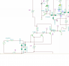
Er Um! can you take another look at your circuit. You have t7 and t8 collectors connected together and from there have a direct connection to the booster transistor. It is DIRECT. It is a wire. In parallel with that wire you have a pot. What is the function of that shorted pot?
If TINA did not flag this non-function it gives me pause to conclude that it's just a toy. That is why it's free. iiiiiiiieeeeeeAAAAAAAA!!!!
Take out the pot. Insert 0.1 micro farad cap across shunting diodes (t7 base and ground). Then tell TINA that the transistors are not just NPN. Tell TINA that they are specifically 2N3904s or 2N2222As. Then place an LED and 500ohm resistor in the collector of the driver transistor. Measure the current when the driver is off. trigger the twin-t and measure again. The LED should be on. Not dim but fully on (15 to 20 Ma).
Then calculate the signal controller's resistive load. Because that will be what the driver transistor will have to handle. Remember that load will vary too. (ie what is the load when green is on, what is it if yellow is on, what is it if yellow is enabled, green is off and red is on) The lowest value is what the driver transistor has to handle. from what I see it should be OK.
P
NOTE: If you have given TINA the circuit I sent, with components indicated, and TINA says it won't work, tell TINA to go back to school and take up brick laying. It's working fine on my work bench.
in Petes post https://www.electro-tech-online.com/attachments/twin-t-prototype-pdf.36615/
the collectors are connected together as are my T7 and T8
Angi, try the detect circuit by itself (one of the files I Emailed you.. The one with an LED connected to the last transistor.
are you saying the third transistor (from left) is not supposed to be connected directly?
if so, then why is it conneced directly as per schematic (see link if i got the right link schematic??
the pot, after looking at it, I must have it connected wrong as I was following Angis description several posts back.
will look at that but It works for some reason.
In my trials I think I connected the pot from the T&/T* collectors to the collector of ???
will get back to you.
Time to do a little trouble shooting here. We have a real simple circuit that for some reaswon isn't doing what it aught.
Angie.
When I draw 1/2 amp across the track my twin-t collectors are close to 0 volts. When I put 4.7k acrosss the track I read 0.1 volts at the Twin-t collectors.
When my track is clear the collectors are at 0.7 volts.
Angie.
Please put a ground into the input of your signal controller. See if the green is completely out. Then see if the red is fully on. Then check the two yellows. See if they are on. If all is well then we know that the twin t is not delivering the full ground that your controller needs. Now deliver the full ground to the sig controller via a power diode. (0.7 volt drop -- remember). If the LEDs are misbehaving then your signal controller actually needs a rail to rail ground. So what to do. MrDeb sent you a site which a controller which has a similar circuit to yours. Lots of diodes and transistors. But at the bottom of the page the detect is a mechanical switch, probably from a relay. It too needs a full current bearing, 0 volt ground.
Let's find out where the problem is. Is it the twin-t or the sig controller.
It just dawned on me that the circuit that Pete posted and the one I just posted are almost identical.
exception = I don't have R3 or R4, no relay or capacitor
R2 is 4.7k in Petes where I have 3.2k
all else that I can see are same or ??
with 36 ohms across track (caculates .5ma) amp =451.82ma
with 4.7k across track = collectors VF7 = 17.02mv
track clear = 825.99mv
trying to duplicate Petes readings . CLOSE for sure
in Petes post https://www.electro-tech-online.com/attachments/twin-t-prototype-pdf.36615/
the collectors are connected together as are my T7 and T8
Angi, try the detect circuit by itself (one of the files I Emailed you.. The one with an LED connected to the last transistor.
are you saying the third transistor (from left) is not supposed to be connected directly?
if so, then why is it conneced directly as per schematic (see link if i got the right link schematic??
the pot, after looking at it, I must have it connected wrong as I was following Angis description several posts back.
will look at that but It works for some reason.
In my trials I think I connected the pot from the T&/T* collectors to the collector of ???
will get back to you.
I think the twin-t is working fine. The output, designed to operate a relay, is not sufficiently close to absolute ground. (0.7 volts, I bet) that the LEDs are 'sharing' current. All the transistors in the controller are referencing absolute ground. Maybe putting low value resistors (or even diodes) in the transistor emitters might lift them enough so that a base voltage of 0.7 volts will cut them off. If you apply a ground to the input of the controller and everything works then we have the nub of the problem.
P.
Please put a ground into the input of your signal controller. See if the green is completely out. Then see if the red is fully on. Then check the two yellows. See if they are on. If all is well then we know that the twin t is not delivering the full ground that your controller needs. Now deliver the full ground to the sig controller via a power diode. (0.7 volt drop -- remember). If the LEDs are misbehaving then your signal controller actually needs a rail to rail ground. So what to do. MrDeb sent you a site which a controller which has a similar circuit to yours. Lots of diodes and transistors. But at the bottom of the page the detect is a mechanical switch, probably from a relay. It too needs a full current bearing, 0 volt ground.
The signalling circuits on the own, linked as blocks 1 and 2 work fine. I have switches in the circuits that are connected from the detect line to ground. When pressed the red comes on, green goes out completely.
Does this answer the question? If not explain better (i.e. words of one syllabal) as I have no idea what you mean by 'Please put a ground into the input of your signal controller'.
Do you want me to connect the 12V to gnd direct??? Sounds a little over the top.
NoI just wanted you to fake a detect by grounding the input to your signal controller. But I guess you answered my question. How were the yellows by the way.
Hm! seems that the twin-T circuit is good enough to latch a relay but not good enough to supply a pure ground to other electronics. Opto-isolator all over again. I'm going to ask Bill about this. Stay tuned.
This site uses cookies to help personalise content, tailor your experience and to keep you logged in if you register.
By continuing to use this site, you are consenting to our use of cookies.

")