Continue to Site

Welcome to our site!

Electro Tech is an online community (with over 170,000 members) who enjoy talking about and building electronic circuits, projects and gadgets. To participate you need to register. Registration is free. Click here to register now.

  • Welcome to our site! Electro Tech is an online community (with over 170,000 members) who enjoy talking about and building electronic circuits, projects and gadgets. To participate you need to register. Registration is free. Click here to register now.

200 MHz Triangular Wave

Status
Not open for further replies.
Hi,

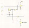
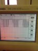
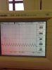
I was tasked to design a circuit to generate a triangular waveform or sawtooth waveform as a carrier signal. I referred to quite amount of circuits but never got them to work exactly. The closest I get was using a LM741 to generate a slightly distorted sawtooth wave. And I heard that LM741 isnt suitable for too high frequency?
 
Did you search this forum? There is a good thread about generating triangular/sawtooth signal. Just only a week old thread.
 
200mhz?
The LM741 is orders of magnitudes too slow.
Look at current feed back amplifiers.
You need a amplifier that can operate well at 200mhz.
 
Last edited:
Well, the 741 will work at 200mHz; just not at 200MHz ;)
I see.
I found this schematic that I tried out myself in the lab. It worked fine but how do you determine the output frequency of the tri-wave?
The comparator used was LM324N. I understand that LM324 is not able to work at 200MHz but just wanna try out the circuit.
 

Attachments

  • Tri-WaveGEN.JPG
    Tri-WaveGEN.JPG
    28.3 KB · Views: 667
Hi,

If you want to start with the LM324 then you should keep the frequency down near maybe 2kHz or something low like that.

The frequency calculation involves calculating the ramp time up and the ramp time down and adding them together. The ramp times are dependent on the resistor and capacitor used for the integrator and the threshold settings of the comparator. The calculations are pretty simple because it is a ramp. The comparator has two threshold settings we can call v1 and v2. The ramp goes from v1 up to v2, then back down to v1. The total time is the period and 1/period is the frequency.

If you like we can go through these calculations, there isnt that much to them really. In the simplified ideal circuit the period is 2*R1*C so the frequency is 1/(2*R1*C) but this can change significantly with choice of op amp, and that also assumes R2=R3/2 exactly.
 
Last edited:
A lousy old LM741 is 45 years old and has trouble above only 9kHz.
A lousy old LM324 is very slow and has trouble above only 2kHz but it also has crossover distortion that puts a "hiccup" in the middle of a waveform.

200MHz is a very High Radio or TV frequency and to make a 200MHz triangle wave you need an amplifier that goes up to 4GHz or higher.
 
Hi,

If you want to start with the LM324 then you should keep the frequency down near maybe 2kHz or something low like that.

The frequency calculation involves calculating the ramp time up and the ramp time down and adding them together. The ramp times are dependent on the resistor and capacitor used for the integrator and the threshold settings of the comparator. The calculations are pretty simple because it is a ramp. The comparator has two threshold settings we can call v1 and v2. The ramp goes from v1 up to v2, then back down to v1. The total time is the period and 1/period is the frequency.

If you like we can go through these calculations, there isnt that much to them really. In the simplified ideal circuit the period is 2*R1*C so the frequency is 1/(2*R1*C) but this can change significantly with choice of op amp, and that also assumes R2=R3/2 exactly.

I see. Thanks MrAI. With the triangular waveform, I input to another comparator on the non-inverting input and a sine wave on the inverting input. It should have a PWM output but the waveform seems distorted. Do you have any idea on why?
 

Attachments

  • PWM SCH.JPG
    PWM SCH.JPG
    39 KB · Views: 545
  • 2013-10-24 10.21.23.jpg
    2013-10-24 10.21.23.jpg
    1.3 MB · Views: 486
A lousy old LM741 is 45 years old and has trouble above only 9kHz.
A lousy old LM324 is very slow and has trouble above only 2kHz but it also has crossover distortion that puts a "hiccup" in the middle of a waveform.

200MHz is a very High Radio or TV frequency and to make a 200MHz triangle wave you need an amplifier that goes up to 4GHz or higher.
I see. Then is there any high freq op-amp recommendation for use?
 
Opamps are not used for very high frequency radio and TV and certainly not for microwave frequencies.
 
Last time I made a fast triangular waveform:
Buffer amp=TLV3501 I use 1ghz to 2ghz amplifiers. I have seen 10ghz op-amps.
Current sources (one pulling up and one pulling down)= MMBTH81 and MMBTH10 fast low capacitance transistors.
Stearing diodes = HSMS-286
Timing cap=22pf

I could not get the current sources to turn on/off as fast as I needed. so.... I keep both current sources on all the time (one pulls up and one pulls down). Through low cap diodes I steel away current from one of the current sources.

You can not bread board this! One inch of wire will cause trouble. You probably can't use through hole parts. This is not a hobby project.
 
I see. Thanks MrAI. With the triangular waveform, I input to another comparator on the non-inverting input and a sine wave on the inverting input. It should have a PWM output but the waveform seems distorted. Do you have any idea on why?

Hi again,

Yes. Your input sine wave operates around a different bias point than the output triangle from the op amp. In an ideal circuit built like that the output triangle does not go from zero to +Vcc, it goes from Vcc/4 to 3*Vcc/4 and is centered around Vcc/2. Now if the sine goes from some negative peak to some positive peak then you'll only see PWM during the time when the sine is between Vcc/4 and 3*Vcc/4, and the rest of the time the output will either be high or low.

So to get it to work better you'll have to add an offset to the sine wave to get it to reside between the two levels above. With a 5v power supply that means the triangle ramps between 1.25v and 3.75v (ideal circuit) so the sine wave levels would all have to be within that range.

That's for an ideal circuit with exact values and perfect rail to rail op amps. For the LM324 for example the output does not reach all the way to +Vcc so it causes the triangle to run between somewhat different levels. So it might be best to measure those levels and then determine what is best for the sine wave. The sine wave will need a DC offset and also limited amplitude. We can calculate those requirements or you can measure the triangle.

Note however that with an imperfect op amp like that the triangle will not be symmetrical either. It's ramp up time could be quite different from it's ramp down time. That may or may not bother your output PWM signal. For a more symmetrical triangle use a rail to rail op amp or we'll have to do some calculations to see what we can adjust to get it right with the cheaper op amps.

One more note, since C=5uf (approximate) and R1=1k, the output triangle frequency is approximately:
f=1/(2*R1*C)=1/0.010=100Hz. This means your sine wave will have to be around 5Hz if you want to see 10 pulses per half cycle. If you use a faster triangle you can use a higher frequency sine wave, but you'll have to stay within the operating range of the op amp.

Also, if you use a power supply voltage which is higher than 5v (like 10v) you'll see a more symmetrical triangle even with the cheaper op amp assuming you still stay within the operating range of the op amp. The slew rate determines the fastest ramp of the output, but the second part (the comparator used for the triangle) is expected to have a clean rise and fall time which means it has to have a comparable faster slew rate. If the slew rate is too low for that section, the output triangle will look like a partly exponential wave rather than a triangle because R1 will end up getting a current through it that varies during the triangle wave slopes instead of a constant current.
 
Last edited:
Hi again,

Yes. Your input sine wave operates around a different bias point than the output triangle from the op amp. In an ideal circuit built like that the output triangle does not go from zero to +Vcc, it goes from Vcc/4 to 3*Vcc/4 and is centered around Vcc/2. Now if the sine goes from some negative peak to some positive peak then you'll only see PWM during the time when the sine is between Vcc/4 and 3*Vcc/4, and the rest of the time the output will either be high or low.

So to get it to work better you'll have to add an offset to the sine wave to get it to reside between the two levels above. With a 5v power supply that means the triangle ramps between 1.25v and 3.75v (ideal circuit) so the sine wave levels would all have to be within that range.

That's for an ideal circuit with exact values and perfect rail to rail op amps. For the LM324 for example the output does not reach all the way to +Vcc so it causes the triangle to run between somewhat different levels. So it might be best to measure those levels and then determine what is best for the sine wave. The sine wave will need a DC offset and also limited amplitude. We can calculate those requirements or you can measure the triangle.

Note however that with an imperfect op amp like that the triangle will not be symmetrical either. It's ramp up time could be quite different from it's ramp down time. That may or may not bother your output PWM signal. For a more symmetrical triangle use a rail to rail op amp or we'll have to do some calculations to see what we can adjust to get it right with the cheaper op amps.

One more note, since C=5uf (approximate) and R1=1k, the output triangle frequency is approximately:
f=1/(2*R1*C)=1/0.010=100Hz. This means your sine wave will have to be around 5Hz if you want to see 10 pulses per half cycle. If you use a faster triangle you can use a higher frequency sine wave, but you'll have to stay within the operating range of the op amp.

Also, if you use a power supply voltage which is higher than 5v (like 10v) you'll see a more symmetrical triangle even with the cheaper op amp assuming you still stay within the operating range of the op amp. The slew rate determines the fastest ramp of the output, but the second part (the comparator used for the triangle) is expected to have a clean rise and fall time which means it has to have a comparable faster slew rate. If the slew rate is too low for that section, the output triangle will look like a partly exponential wave rather than a triangle because R1 will end up getting a current through it that varies during the triangle wave slopes instead of a constant current.

Hi, thanks. I understood what you meant.
and also, there is this spiking in the triangular waveform and the amplitude is not constant. Is there any solution to it?
The capacitor value i used was 330nF. And R1 = 1k
 

Attachments

  • 2013-10-25 10.33.13.jpg
    2013-10-25 10.33.13.jpg
    1.2 MB · Views: 450
  • Tri-WaveGEN.JPG
    Tri-WaveGEN.JPG
    28.3 KB · Views: 447
Yeah. Why?

Your task is to generate 200 Mhz triangle wave and you have to come to this forum for help..? Can't you ask your professor/teacher/instructor for help? That is one serious school project. The purpose of school projects is to learn. Not just to "be happy if it works".
 
Last edited:
Hi, thanks. I understood what you meant.
and also, there is this spiking in the triangular waveform and the amplitude is not constant. Is there any solution to it?
The capacitor value i used was 330nF. And R1 = 1k

Hello again,

You could try lowering the frequency for this 'trial' circuit, and you could also add a post low pass filter to the output so you snub all of those spikes. The post filter would be an RC low pass filter with a cutoff frequency much higher than the triangle wave frequency, like say 20 times higher. The idea is to find values for R and C that meet the following criteria:
1. Reduces the spike to an acceptable level.
2. Do not seriously degrade the triangle linearity. (although slight curves are usually ok).
3. Do not increase the output impedance significantly.

Of course you could try a better op amp eventually too.

Also realize that if this is for a PWM circuit pulse width generator section then you dont have to have a super perfectly linear triangle either. It can have slightly curved sides (concave up or concave down) and work pretty well. That's because the output pulse will still be regulated, it will just change the loop gain slightly for different load and line conditions. A changing loop gain is not something we want, but if it is small enough it doesnt have any significant effect on the actual output pulse width. This is of course when the PWM is used in a negative feedback controlled circuit not in a feed forward only circuit. In a feed forward only circuit the output pulse may vary from the ideal by an amount equal to the difference between the curved triangle and a perfectly linear triangle at the particular control point level, but to predict that we'd have to know the exact triangle waveform.

Spiked peaks may or may not be troublesome to the system. It depends on the width of the spike relative to the minimum response time of the system. If the width is wide it will prevent the system from being able to produce zero output for zero input, but that's not usually a problem either because often there is never a zero input. So it partly depends on what this will be used for and what the min and max levels of the input wave have to be.
 
According to synopsis of the book, your solutions should be within the chapters ....

Focused on the field of knowledge lying between digital and analog circuit theory, this new text will help engineers working with digital systems shorten their product development cycles and help fix their latest design problems. The scope of the material covered includes signal reflection, crosstalk, and noise problems which occur in high speed digital machines (above 10 megahertz). This volume will be of practical use to digital logic designers, staff and senior communications scientists, and all those interested in digital design.
 
Status
Not open for further replies.

Latest threads

Back
Top