transistance
New Member
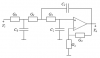
I am trying to build a 3rd order low pass filter. The design that im following uses 1 TL072. Since I could only find TL071 in my area i decided to use 2 of those to replace the dual opamp. My circuit is still not behaving properly though. When I'm doing this conversion am I missing something? The TL072 has no offset pins while the TL071 has 2 for each. I just connected these offsets to ground both on both chips. Am I doing something wrong there?
This is my first time building a filter on my own after college, so I'm trying to relearn some stuff. I am thinking that the cap and res tolerances when combined might be throwing my filter off.
Thanks in advance,
This is my first time building a filter on my own after college, so I'm trying to relearn some stuff. I am thinking that the cap and res tolerances when combined might be throwing my filter off.
Thanks in advance,
")