Electro Tech is an online community (with over 170,000 members) who enjoy talking about and building electronic circuits, projects and gadgets. To participate you need to register. Registration is free. Click here to register now.
Welcome to our site! Electro Tech is an online community (with over 170,000 members) who enjoy talking about and building electronic circuits, projects and gadgets. To participate you need to register. Registration is free. Click here to register now.
The coil contains energy that has to go somewhere; it has to be awfully slow to keep the voltage reasonable. You'd need a resistor in parallel with the coil (where the diode was).
correction: My bad: The energy goes into the transistor! With a slower turn-off time this is a graceful process and nothing is hurt.
Still, a resistor across the coil, as you mentioned, is not a bad place to dump the energy if one can tolerate some wasted power in the resistor. If the resistor has the same value as the resistance of the relay coil, the flyback voltage will never be greater than about twice the voltage applied across the relay coil when the transistor is turned on. The bonus with the resistor is the slow contact release time is largely reduced (compared to a diode) which can save the contacts from spot welding upon opening. And a resistor is less expensive than a diode or a capacitor.
Still, a resistor across the coil, as you mentioned, is not a bad place to dump the energy if one can tolerate some wasted power in the resistor. If the resistor has the same value as the resistance of the relay coil, the flyback voltage will never be greater than about twice the voltage applied across the relay coil when the transistor is turned on. The bonus with the resistor is the slow contact release time is largely reduced (compared to a diode) which can save the contacts from spot welding upon opening. And a resistor is less expensive than a diode or a capacitor.
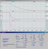
Here is a comparison of three different Snubbers. Note the relative release time of the three methods (current through the respective coils). The RC method is the fastest release, and doesn't add to the current when the relay is pulled in like the resistor only does. The magnitude of R4 & R5 determine the voltage overshoot, which must be kept within the breakdown voltage of the switch (transistor, fet). Higher values of R4 & R5 shorten the release time at the expense of even higher peak voltages.
You didn't model the diode + zener I mentioned they use in high end devices to achieve fastest release times?
With the zener as high as possible, say 36v zener when using most 45Vce small switching transistors.
You didn't model the diode + zener I mentioned they use in high end devices to achieve fastest release times?
With the zener as high as possible, say 36v zener when using most 45Vce small switching transistors.
hi,
I also noticed that when using R/C subbers, thought it may be an artefact from Spice.
I avoid using the zener/diode clamp when logic circuits are close by, the 30V 'spike' can radiate a fair distance.
I have only used this combination, when clamping solenoids, its too noisy.
Perhaps you recall the old style paper tape punches, if the punch pin retracted too slowly you got a tape tear/jam.
I had to play with the R and C values to get the highly damped waveform in the Spice sim I posted yesterday. The Ratio of R to coil resistance sets the peak value. Higher values of R increase damping. C sets the slew rate and smaller C reduces damping. To optimize R & C in a practical circuit, you would have to know coil inductance and resistance.
A diode can also be placed in series with a resistor to avoid the wasted power in the resistor, yet still largely improve contact release time over a diode alone across the coil.
The peak flyback voltage will be the resistor value multiplied by the relay coil operating current. The larger the resistor, the better.
A diode can also be placed in series with a resistor to avoid the wasted power in the resistor, yet still largely improve contact release time over a diode alone across the coil.
The peak flyback voltage will be the resistor value multiplied by the relay coil operating current.
Re the ringing, in actual use the circuit performs better than the simulation. Relays have massive iron losses, as the stator is a pressed mild-steel bit of garbage generally, not a proper magnetic core material like a simulated inductor.
So in real life the huge iron losses act like a big damping factor on the flyback energy (which should be less/faster than you show in the sim) and also damp the ringing which i have never seen on the cro.
Probably too late to comment since last post on this thread was a month ago.... but...
I got into the habit of using a series resistance between the collector and the coil. I pick a small resistance such that the voltage across the coil is still above the min spec holding voltage, considering it forms a voltage divider twixt the coil resistance and the resistor. Consider also the voltage is max when the transistor switches on (since i=0 initially), and reduces as current increases -- just what we want. Now the flyback diode is sometimes inside a driver (like ULN2003 or 2803) where I may tie the cathode side to 12V, for instance, while the coil is a 5V coil. I like to make use of such built in clamp diodes and the series resistor and option to clamp at higher voltage is what make a simple diode clamp work better (vis a vis the slowing of contact opening due to back emf).
The advantages are that the coil is not overdriven (keeps down coil temperature and overall current draw) which may be important. Still the initial voltage across the coil is high and falls to only as much as necessary to hold the contacts together. Then when the transistor switches off, the flyback current is not short circuited through the clamp diode so that the contacts can come apart quicker (so make sure your diode anode is on the other side of this resistor) not to mention also clamping to a higher voltage, allowing that much more time for the spring to pull the contacts apart. By and large, the contacts are more damaged by arcing while pulling apart than anything else and to avoid welded contacts may well save other components in a system. Seems worth it to apply more thought than the usual habit of throwing 1N4148s across coils, which is what I used to mindlessly do until I finally started looking at it some more.
I think you are operating under a misconception.
Relays operate on current (actually, ampere*turns), not voltage. The voltage spike you see at turn-on is a by-product of the inductance of the coil. It does not aid in turn-on. A series resistor actually slows the pull-in time.
The resistor does reduce turn-off time, as you noted.
As Roff noted, a series resistor will slow the relay turn on. If you want to limit the operating current but still get fast turn-on, you can put a capacitor in parallel with the resistor between the relay coil and the transistor collector. Pick a capacitor large enough to supply full current through the relay coil during its operate time after the transistor turns on. Then as the capacitor charges, the current will slowly reduce to whatever the resistor and relay coil resistance allows.
When the transistor turns off, the capacitor will discharge through the resistor, ready for the next relay turn-on.
This site uses cookies to help personalise content, tailor your experience and to keep you logged in if you register.
By continuing to use this site, you are consenting to our use of cookies.

")