Continue to Site

Welcome to our site!

Electro Tech is an online community (with over 170,000 members) who enjoy talking about and building electronic circuits, projects and gadgets. To participate you need to register. Registration is free. Click here to register now.

  • Welcome to our site! Electro Tech is an online community (with over 170,000 members) who enjoy talking about and building electronic circuits, projects and gadgets. To participate you need to register. Registration is free. Click here to register now.

10x7 LED SignBoard (MERRY X MAS)

Status
Not open for further replies.

Gayan Soyza

Active Member
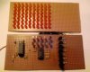
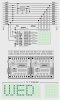
I built a 10x7 led signboard using PIC16f84a.just to get some experience in making moving signs.It consist of count down,scaning from left & right,hold on display,elevator method,adding letters......etc.

Unfortunately I coudn't find any led matrix so I used normal 5mm led's.no mo memory space in the pic to add more patterns only 2 lines left in program memory.

see the attachment for a small video.
 

Attachments

  • 10x7 Display.zip
    554.4 KB · Views: 3,329
  • 10x7 Signboard.JPG
    10x7 Signboard.JPG
    285.4 KB · Views: 3,264
Gayan Soyza said:
Unfortunately I coudn't find any led matrix so I used normal 5mm led's.no mo memory space in the pic to add more patterns only 2 lines left in program memory.

So why use a prehistoric PIC?, simply changing it for it's 'modern' replacement the 16F628 doubles your program memory.
 
Moving sign

I have built a similar one using a Parallax Basic Stamp II and also ported it over to a Parallax SX-28 microcontroller. Both are written in their version of BASIC and use 4017 chips and transistor/chip buffers to drive the LEDs across. I have built a custom 20 x 7 and want to build a larger one sometime. It only scrolls (lettters, symbols or whatever) from right to left. Do you have a schematic of yours. I am not a PIC programmer but would like to see how you did it. I spent a lot of time learning this as there wasn't too much available on the web about this. Any schematics and code would be nice too.

Thanks,

Tim
 
Check my PIC tutorials, the latest one implements an 8x8 matrix of LED's, with full alphanumeric fonts and four way scrolling - there's also a couple of videos of it working.
 
Judging by a diagram Gayan Soyza posted a while back, I think it's based on this design : **broken link removed**
 
tdg8934 said:
I have built a similar one using a Parallax Basic Stamp II and also ported it over to a Parallax SX-28 microcontroller. Both are written in their version of BASIC and use 4017 chips and transistor/chip buffers to drive the LEDs across. I have built a custom 20 x 7 and want to build a larger one sometime. It only scrolls (lettters, symbols or whatever) from right to left. Do you have a schematic of yours. I am not a PIC programmer but would like to see how you did it. I spent a lot of time learning this as there wasn't too much available on the web about this. Any schematics and code would be nice too.

Thanks,

Tim
Hi Tim,

I'd be happy to share a slightly more advanced design if you're interested.

This design with 9 pin interface will drive one to seven 8x8 matrices to full brightness. It uses the PWM signal from the PIC for brightness control and to multiplex the 8 pin PORTB "row driver" bus with the '5821 column driver "CLK" and "DAT" lines to allow loading the shift registers on up to seven '5821 column driver ICs in parallel in about 24 cycles (4.8 usecs).

I can provide simple interrupt driver examples in another post, if you're interested.

Happy Holidays. Mike

matrix-display-9-pin-design-png.10695


Attachments

  • Matrix Display (9 pin design).PNG
    Matrix Display (9 pin design).PNG
    34.1 KB · Views: 6,960
  • Matrix Display (10 pin design).PNG
    Matrix Display (10 pin design).PNG
    34 KB · Views: 949
Last edited:
Hi again Tim,

Just thought I'd mention that I've used an 8-pin interface version of this design in the past using a 16F88 with the RB0 pin configured as the CCP1 PWM output. I've included a drawing that shows how one might wire up 5x7 type LED modules.

There's also a TI serial-to-parallel sinking driver IC with 150-ma outputs which I suspect may work well in these designs. It's the TPIC6B595. I have samples but have not tried them yet.

Regards, Mike

matrix-display-8-pin-design-png.10716
 

Attachments

  • Matrix Display (8 pin design).PNG
    Matrix Display (8 pin design).PNG
    33.6 KB · Views: 6,885
Last edited:
SX-28 and / or Basic Stamp 2 LED Moving Display Sign

Mike,

A very impressive design!

Here are my designs for a 20x7 display (attached zip).

I have also tried using the MAX7219 chip to drive more than 64 LEDs but can't figure out how to cascade 2 or more of them.

Currently I am working on a SX-28 (7 rows) and 8255 PIA (up to 24 columns) version and have working code to send data out to the 24 LEDs but need to work on the scanning. I am trying to not use a 4017 and only an SX-28 microcontroller and a 8255 chip but I cant figure out how to send data to RB and RC at the same time unless an interupt is used. Otherwise 1 row has data for every collumn and it needs some scanning on the 7 rows I think for persistance of vision.
 

Attachments

  • MovingLEDv1_1.zip
    168.2 KB · Views: 1,809
can u make this circuit for moving text usnig MAX6952 or MAX6953,
i need them,i want to make thse moving text display in Proteus,
can u help me,
 
tdg8934 said:
Mike,

A very impressive design!

Here are my designs for a 20x7 display (attached zip).

I have also tried using the MAX7219 chip to drive more than 64 LEDs but can't figure out how to cascade 2 or more of them.

Currently I am working on a SX-28 (7 rows) and 8255 PIA (up to 24 columns) version and have working code to send data out to the 24 LEDs but need to work on the scanning. I am trying to not use a 4017 and only an SX-28 microcontroller and a 8255 chip but I cant figure out how to send data to RB and RC at the same time unless an interupt is used. Otherwise 1 row has data for every collumn and it needs some scanning on the 7 rows I think for persistance of vision.
Hi Tim,

Nice design and nice schematics. A few comments;

<1> Too many chips (grin).

<2> It seems you're scanning columns for a 1/20th or 5% duty cycle but the ULN2003 sinking column drivers you've chosen limit peak current in any column to about 500-ma. Unfortunately with a 5% duty cycle you'd need to sink a peak current of approximately 200-ma/LED or 1.4-amp/column for full brightness. You really should consider a design that scans rows at a 1/7th or 14% duty cycle or scans columns at a 1/8th or 12.5% duty cycle.

<3> I'm surprised you're not using an interrupt driver which reduces display management to a simple "low overhead" background task allowing your main program to simply stuff the display buffer.

~~~~~~~~~~~~~~~

There are many different ways to drive large LED matrices. Here's another example that's a bit more modular.

Instead of driving and scanning one large row I scan columns at a 1/8th or 12.5% duty cycle. Each 8x8 module has it's own row driver/latch and column driver transistors. All of the column 1's in each module are driven at the same time, then all of the column 2's, etc. Current requirements for full brightness at a 12.5% duty cycle are approximately 80-ma/LED or 640-ma/column per module. Instead of using eight large 10-amp column driver PFETs for the entire matrix of modules I decided to use eight small 2.4-amp column driver PFETs for each individual module to reduce size and heat dissapation. Anyway, I'm sure you get the idea.

Regards, Mike

concept-clock-8x8-jpg.10734
 

Attachments

  • Concept - Clock 8X8.JPG
    Concept - Clock 8X8.JPG
    141.8 KB · Views: 7,124
EPE recently did a similar project, with a PIC 16F628 on each board, and the displays stacking together just like that. It can have 128 boards stacked together, all fed from one master board with a 16F628 and a MAX232 for a PC connection.
 
hi look at my circuit and code but its not working,its built in Proteus,and Protgramming in Mikroc
can u correct the problem,?
 

Attachments

  • MAX6952.zip
    52.5 KB · Views: 776
Sorry, I don't have either so can't even look at your schematic or code. Perhaps another Forum member can take a look.

Regards, Mike
 
Nigel Goodwin said:
EPE recently did a similar project, with a PIC 16F628 on each board, and the displays stacking together just like that. It can have 128 boards stacked together, all fed from one master board with a 16F628 and a MAX232 for a PC connection.

Unfortunately, referencing an EPE article has little value if you're not a subscriber. Too bad.
 
Mike said:
Unfortunately, referencing an EPE article has little value if you're not a subscriber. Too bad.

You can buy back issues at reasonable cost, and even PDF versions! - if you're using PIC's you SHOULD be subscibing to EPE, they publish more PIC projects than other magazines - and in any case, the software is always available for free download.
 
Hi Mike, K8LH

I really like your designs for the led matrices. What software do you use to create the pretty schematics? also you can get an online subscription to EPE for about $20 a year, they seem to get most of their projects from Silicon Chip magazine but they still have some good articles and what not.
 
hi,
look at my circuit and code built in MikroC,
it shows "ali raza" scrolling,
plz review code to optimize it,
can u seggest any instruction from data sheet to scroll the text,
in this example the text is scrolling one matrix at a time,i want to scroll it one column by column,
thanx,
 

Attachments

  • MAX6952-old.zip
    51 KB · Views: 568
Wish u a Very Happy New Year Folks....

Wow.....Some Nice Advanced Methods.

Do u have any other IC's same like MIC5821 or 4017 which has more outputs to Drive LED Matrix.I mean 4017 has only 10 outputs.I coudn't find (MIC5821) in my place.Adding 3 or 4 IC's (4017) will make the cct bigger & must add more Delays for Clk & Reset for each IC's in the Program when Shfting Columns.

Do u know an IC which has 20 (or closer) output pins,which has same options like Clk in & Reset.& also I like to have the datasheet of MIC5821

Thankx.....
 
Status
Not open for further replies.

New Articles From Microcontroller Tips

Back
Top