Continue to Site

Welcome to our site!

Electro Tech is an online community (with over 170,000 members) who enjoy talking about and building electronic circuits, projects and gadgets. To participate you need to register. Registration is free. Click here to register now.

  • Welcome to our site! Electro Tech is an online community (with over 170,000 members) who enjoy talking about and building electronic circuits, projects and gadgets. To participate you need to register. Registration is free. Click here to register now.

1 sec pulse from 30 sec clock

Status
Not open for further replies.

markelectro

New Member
Hello to all

I have a Gent master clock that has 30 sec impulsing. This gives an impulse to slaves 2 x per minuet.
The 30 sec pulse you will see from the link is obtained from a wheel that has 30 teeth , one of the teeth is longer than the rest causing the pendulum to knock the rest from the impulse arm thus causing a pulse.

**broken link removed**

I have a 1 sec polarising slave that I would like to run from the master clock, unfortunately this clock does not have 1 sec pulses to the slaves. the slave does require a pulse length of around 0.7 sec for it to work and is 24v 3000 ohms

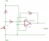
I was thinking of an electro circuit that could maybe wired into the wiring of the clock that would give out 1 sec AC. pulses. Or sensors that could watch the 30 toothed count wheel and at each tooth a pulse is triggered.

What ever way we arrive at it must be governed by the clocks pendulum and not an external circuit like a crystal oscillator.

I do have clocks that use reed switches in other clock but I think this one needs to be different.

I do have a PIC. programmer but at the moment I don't have the asm. knowledge.

I would welcome any thoughts and advice.

Regards Mark
 
Last edited:
This sounds good

sensors that could watch the 30 toothed count wheel and at each tooth a pulse is triggered.
How large are the teeth? They make slot detectors which combine a led and a detector in a single unit. If the teeth are large enough one would slip over the edge of the gear.

-
 
Last edited:
3v0 said:
This sounds good


How large are the teeth? They make slot detectors which combine a led and a detector in a single unit. If the teeth are large enough one would slip over the edge of the gear.

-

3V0

Thanks for the reply.

Just been to measure the teeth. from the circular face they are only approx 1mm or so high and are around 7mm in length.

Sound interesting but are they big enough?

will be good if we can figure something out.

The simple solution is to use reed switches to register when the pendulum swings two and fro.

Regards Mark

Regards Mark
 
3v0
Some would say use a PIC. When the Master clock impulses,it will short out the processor causing a restart. The circuit would then generate 30 pulses for the bipolar quartz motor. On the next impulse interval, it would reset and do it again.

Unfortunately this is beyond my level.I do have a PIC. programmer but don't have the programming knowledge.

Can anyone help?


Mark
 
Everything you mentioned could be made to work.

I think the teeth are wide enough. You could run fiber optics
up to the gear teeth. Forest M. Mims has just this sort of thing
in at least one of his books. Circuit Scrapbook II on pages
169-170. Simple circuit with an op amp and a transitor. The
detector is made from a bit of fiber optic cable, an LED and a
phototransistor.

If you are serious I will post the schematic.


What is your goal for this and which solution is the best fit.

Figure out which way you want to go.
 
Last edited:
3v0 said:
Everything you mentioned could be made to work.

I think the teeth are wide enough. You could run fiber optics
up to the gear teeth. Forest M. Mims has just this sort of thing
in at least one of his books. Circuit Scrapbook II on pages
169-170. Simple circuit with an op amp and a transitor. The
detector is made from a bit of fiber optic cable, an LED and a
phototransistor.

If you are serious I will post the schematic.


What is your goal for this and which solution is the best fit.

Figure out which way you want to go.

3V0

My goal is to impulse a 1 sec AC. slave like a modified quartz movement from the 30 sec countwheel.The count wheel will move in 1 sec increments and normally impulses 2 x in 1 min but I require 1 sec pulses.As stated I want this to work from the count wheel so I do like the sound of your solution.

Pic's are somwhat esier if you know how to pograme them,unfortunatly I don't.

If you can provide details of the schematic I would be very pleased to try this out.


Regards Mark
 
This is a starting point. The opamp outputs should switch when you place an LED in front of the phototransistor T1. Once that works you should be able to put T1 on one side of the gear and an LED on the other. You may have to fudge with it to get it to work when the gear is rotated. Perhaps a mask in front of T1 the size of the hole between the teeth to block out stray light.


Radio Shack should have all the parts.

I am not an analog person. There are others who will correct this if I got it wrong.
 

Attachments

  • lightDetectSm.jpg
    lightDetectSm.jpg
    25.2 KB · Views: 311
Last edited:
If you decide to go the pic route, a little more info would be useful.
Which pic do you have?
How accurate do the pulses need to be? Is 29 pulses of 1.01 seconds + 1 pulse of 0.7 seconds accurate enough. This is internal oscillator (1%) accuracy. If not, a crystal would be required.
Are there any power restrictions? Battery powered etc.
How long is the pulse from the existing mechanism?

Mike.
 
I don't know much about pics but i have built an electromechanical tacho generator which generates my alternating 1 second impulses to drive my T&N and CT Wagner and FAVAG one second slave clocks.

The principle i used is similar, timewise, as used at the German railways by T&N so called "Schleichenden Sekunden".
I run an ac synchronous motor with a geartrain generating 60 impulses in 58.6 seconds.
The impulses are picked up from a small disc with black marks sensed via two opto sensors (used in kWh meters to read a black mark from a disc in a meter.)
These give me the alternate impulses.
Via an electronic driver i amplify these to 24 volts / 2 ampères to be able to drive many slave clocks.
A cam will open a micro switch, the motor stops, and waits for the next minute impulse from the master via a 24 volt relay, which overrides the microswitch and the process starts again.

It looks quite good, the seconds hand click happily away up to the 12, waits just over one second, the minute hand advances, then the second hand starts moving again.

There may be easier ways to accomplish this, but electronics and electric clocks are a hobby of mine, so time is not an issue and i fiddle around with these projects when the kids are asleep and my wife visits her forums on the internet. :D
 
Last edited:
3v0 said:
This is a starting point. The opamp outputs should switch when you place an LED in front of the phototransistor T1. Once that works you should be able to put T1 on one side of the gear and an LED on the other. You may have to fudge with it to get it to work when the gear is rotated. Perhaps a mask in front of T1 the size of the hole between the teeth to block out stray light.


Radio Shack should have all the parts.

I am not an analog person. There are others who will correct this if I got it wrong.

3V0 thankyou

It sounds a good solution.I will certainly give it a go and see what comes of it.
Please give me time to experiment and I will let you know how it goes.

If you think of any other ways please let me know.

Regards mark
 
Pommie said:
If you decide to go the pic route, a little more info would be useful.
Which pic do you have?
How accurate do the pulses need to be? Is 29 pulses of 1.01 seconds + 1 pulse of 0.7 seconds accurate enough. This is internal oscillator (1%) accuracy. If not, a crystal would be required.
Are there any power restrictions? Battery powered etc.
How long is the pulse from the existing mechanism?

Mike.

Mike thanks for the reply


To try and answer and I will do my best .

I would use Pic as always seems to be the best route.
I would use the 16fxxxxx range but I do have a programmer that will do mid to high level Pics so any you advice should be ok.

Got to look at what my slave requires to work-

24v 3000 ohms alternating polarity current.I will reqire approx and I say approx 0.7 because a slightly longer pulse would not matter too much. so I think your sugestion of 1x 0.7 and 1x 1.01 would be ok

Alternativly I was thinking of using a modified quartz movement of 1.5v also requiring the alternating palarity but require much les impulse time on each pulse. approx 300ms but I will stand corrected.

The power to the master is max 12v but can use as little as 6.5 but if I were to use the 24v slave then the power would be 24v.

Hope this helps.Please say if not

Looking forward to the reply.

Kind regards Mark
 
markelectro said:
3V0 thankyou

It sounds a good solution.I will certainly give it a go and see what comes of it.
Please give me time to experiment and I will let you know how it goes.

If you think of any other ways please let me know.

Regards mark
If you are comfortable with using a PIC I would go that route. You do not have to fiddle with the optics to make it work. On the other hand you get to play with fiber optics. It is your call.

The code for the PIC should be quite simple. Either way you need to condition the output signal to generate what the other clock needs.
 
RODALCO said:
I don't know much about pics but i have built an electromechanical tacho generator which generates my alternating 1 second impulses to drive my T&N and CT Wagner and FAVAG one second slave clocks.

The principle i used is similar, timewise, as used at the German railways by T&N so called "Schleichenden Sekunden".
I run an ac synchronous motor with a geartrain generating 60 impulses in 58.6 seconds.
The impulses are picked up from a small disc with black marks sensed via two opto sensors (used in kWh meters to read a black mark from a disc in a meter.)
These give me the alternate impulses.
Via an electronic driver i amplify these to 24 volts / 2 ampères to be able to drive many slave clocks.
A cam will open a micro switch, the motor stops, and waits for the next minute impulse from the master via a 24 volt relay, which overrides the microswitch and the process stops again.

It looks quite good, the seconds hand click happily away up to the 12, waits just over one second, the minute hand advances, then the second hand starts moving again.

There may be easier ways to accomplish this, but electronics and electric clocks are a hobby of mine, so time is not an issue and i fiddle around with these projects when the kids are asleep and my wife visits her forums on the internet. :D

Hello Ray

Seems we are living the same lives at differant ends of the globe.Got any spare rooms as very interested in Newzeland :) I do exactly the same exept my kids are 12 and 17 so not much of an issue looking after them.my wife will be watching the soaps on the tv. so I kere researching.

Seems a very interesting solution you have there.It could take me time to break it down and get to grips what you have done.

Thing is I wanted to stay within the confines of the master clock and use very little materials.

3vo's idea does sound a good start and I will be doing tests with that.
Pics are the best rout if only we knew what was required to get the job done.Pics are very versitile and I would choose this route if I were to get the help and advice.

BTW. trains.sometime ago I swapped a very good 1930 oo Horby Mecano with four carriages and lots of track, the original transformer for a sync master,I do acctually think I come off worst.

All the best Mark
 
3v0 said:
If you are comfortable with using a PIC I would go that route. You do not have to fiddle with the optics to make it work. On the other hand you get to play with fiber optics. It is your call.

The code for the PIC should be quite simple. Either way you need to condition the output signal to generate what the other clock needs.


3v0

Fact is I am only just beginning with Pics and I don't yet have the experience to put ASM. code together,I wished I did as that would be the way forwards.

I will play with your method as I can do that without programing.

Hoping that someone will maybe help with the pic. codes!!

Regards Mark
 
If you want to learn ASM then I suggest you do not spend time on the optical. It would be fun to try but may be tricky to get working,

PIC ASM is not too hard to learn. You can get help here once you start coding. Nigel has a good set of intro PIC tutorials. There is also Newcomers, please read! (PIC regarded) Upd. 0xD post at the head of the microcontroller forum. It lists many additional tutorials.

You will need to install MicroChips free MPLAB to assemble the code then use your programmer and its software to program it.
 
Last edited:
So, if I interpret your specs correctly, your ideal solution would output 24V AC into 3000Ω (8mA) at 1Hz, use a 12V input and be reset every 30 seconds by an external input.

If so, something like a 16F628A with a SN754410 should do the trick.

The 16F628 would manage the timing and the SN754410 will output 24V AC from 12V DC input - actually, it will provide 2 separate outputs if required.

Let me know if this sounds right and I can knock together a schematic and suggest some code.

Mike.
 
Pommie said:
So, if I interpret your specs correctly, your ideal solution would output 24V AC into 3000Ω (8mA) at 1Hz, use a 12V input and be reset every 30 seconds by an external input.

If so, something like a 16F628A with a SN754410 should do the trick.

The 16F628 would manage the timing and the SN754410 will output 24V AC from 12V DC input - actually, it will provide 2 separate outputs if required.

Let me know if this sounds right and I can knock together a schematic and suggest some code.

Mike.

Mike

Thanks , all looks good to me.

I think in these early stages of my programming I would use asm.

Regards Mark
 
3v0 said:
If you want to learn ASM then I suggest you do not spend time on the optical. It would be fun to try but may be tricky to get working,

PIC ASM is not too hard to learn. You can get help here once you start coding. Nigel has a good set of intro PIC tutorials. There is also Newcomers, please read! (PIC regarded) Upd. 0xD post at the head of the microcontroller forum. It lists many additional tutorials.

You will need to install MicroChips free MPLAB to assemble the code then use your programmer and its software to program it.


3v0

just off out now so I will read up on your sugestions when I arrive back.


Thanks Mark
 
This is what I think you need as far as a circuit goes.
I would suggest a 32768Hz watch crystal as the code for PWM becomes fairly simple.

Anyone got a better suggestion for the input.

BTW, I'm currently playing here while my wife is watching soaps. Looks like it's the same the world over.

Mike.
 
Last edited:
Status
Not open for further replies.

New Articles From Microcontroller Tips

Back
Top