Continue to Site

Welcome to our site!

Electro Tech is an online community (with over 170,000 members) who enjoy talking about and building electronic circuits, projects and gadgets. To participate you need to register. Registration is free. Click here to register now.

  • Welcome to our site! Electro Tech is an online community (with over 170,000 members) who enjoy talking about and building electronic circuits, projects and gadgets. To participate you need to register. Registration is free. Click here to register now.

1.5 volt circuit microcontroller

Status
Not open for further replies.

Telemachus

New Member
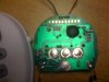
As I am sure several of you are apt to do, I intercepted this egg timer before my wife could throw it away. Lux brand ET50, unfortunately, I can't find any FCC id to lookup schematics.

The piezo buzzer stopped working, but the rest of the electronics seem to work well, and when attached to another buzzer, it works fine (I won't tell her that part, as I now have plans for it).

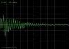
I plan to intercept the output to the piezo with a small PIC, which when the timer goes off, it will ground the shutter button on a canon SLR camera, and then trigger the reset button on the timer to start counting again.

The LCD, microcontroller, and buzzer all work off of a single 1.5 volt AAA battery. I don't see any MAX1674 or MAX7176 that would up convert to 5V, and I can't tell what the IC is without removing the black plug, which might also rip off the chip. I have tested with the voltmeter all around, and it is 1.5volt throughout. Which mictrocontroller do you think they are using at 1.5 volts.
 

Attachments

  • Picture 001.jpg
    Picture 001.jpg
    542.2 KB · Views: 425
It uses a chip on board - the die is mounted directly to the board and is covered with a black blob of resin.

It's not a microcontroller but a custom built low voltage CMOS IC.

This kind of construction is very common in clocks, watches, timers, calculators and electronic toys.
 
That makes sense.

I should still be able to capture the PWM info that is sends to the piezo buzzer, and use a PIC to decode it, right?

The buzzer has no info on it, but putting the attached sound file (recorded from the buzzer going off), it appears to be about 3.5 peaks per ms, which if my math is correct, makes it about a 3.5 khz buzzer.

Should I then assume that what I need to set the PIC to capture is a 3.5khz signal length?
 

Attachments

  • Memo.zip
    92.4 KB · Views: 106
  • Oscope2.JPG
    Oscope2.JPG
    20.9 KB · Views: 243
Last edited:
3.5kHz sounds fine, it's probably an electromagnetic buzzer but it could be piezo.

The reason why I suspect electromagnetic is more likely, is because it tends to be louder at lover voltages because it's lower impedance.
 
Why do you care about the frequency? Don't you just want to know when it's gone off? If there's a signal there at all, it means it's gone off, right?
 
The way the circuit is set up, when the pin on the CMOS goes off at the end of the cycle, it triggers the base of a NPN transistor to connect the collector, connected to the buzzer, to the emittor, connected to ground, in a pulsatile fashion that resonates the buzzer.

Yes, you are right, all I care about is that it goes off, but the CMOS uses such low voltage that my challenge has been to get the pic to read it. A comparator will probably work fine.

Although, now I think that I might be able to get it to work without a pic at all. There is a button that needs to be pushed at the end of the cycle to reset the timer. The button essentially connects a pin on the CMOS to the VDD of the circuit. I think that by using another transistor, I should be able to get the CMOS circuit to reset itself at then end of the timer cycle...
 
I have a question on a circuit that perhaps someone can help me with.

I would like to use add a separate transistor to this circuit, that when the output from the CMOS turns on, it sends signal through to another input pin on the CMOS which tells it to reset itself.

My thought was, connect the output pin of the CMOS to the base of the NPN through a 20k resistor. Connect VDD to the collector of the transistor, and connect the input pin of the CMOS to the emittor. That way, when the small signal from the CMOS goes off, it will let the full voltage of the battery go through to the input pin of the CMOS which in turn resets the timer to restart.

I tried it, and it didn't work. So I though, maybe it needs to be connected to ground on the emittor side? I connected ground to the emittor, and the transistor went up in smoke.

Where am I going wrong here?
 
Your time may be better spent learning how to do this with a microcontroller.
I say this because I think you've got more ideas in your head than making ONE timer circuit in your life. Once you get into microcontrollers, you'll be amazed at what you can do with a $2 chip.
 
I already did...

I guess I should have prefaced this all by stating that I already programmed a pic 12f675 to do this for me. When I was researching LCD screens and push buttons, it was getting more expensive. Although I am no expert at programming pics, my problem lies more in not grasping electronic circuits well, so this so far has been very informative for me.

Thanks.
 
Status
Not open for further replies.

Latest threads

New Articles From Microcontroller Tips

Back
Top