Continue to Site

Welcome to our site!

Electro Tech is an online community (with over 170,000 members) who enjoy talking about and building electronic circuits, projects and gadgets. To participate you need to register. Registration is free. Click here to register now.

  • Welcome to our site! Electro Tech is an online community (with over 170,000 members) who enjoy talking about and building electronic circuits, projects and gadgets. To participate you need to register. Registration is free. Click here to register now.

ramp generator using 555 timer

Status
Not open for further replies.

mdanh2002

Member
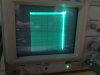
Hi, I am trying to build a VGA-to-scope converted as described in this website **broken link removed** which displays the computer screen on an oscilloscope in X-Y mode with Z input:

**broken link removed**

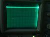
However, it does not work properly. The reason, as I figured out, is the absence of ramp output on X and Y axis (the z-axis output makes sense to me). I only got noises for X and Y axis.

The ramp generator used in the circuit is exactly the same as in this website

555 Timer-Ramp Generator - Electronic Circuits and Diagram-Electronics Projects and Design

**broken link removed**

However, I tried to build the standalone ramp generator with the specified capacitor/resistor values used and still can't get any output. Vout is always 0 volts.

Any ideas what I am missing? Can't believe I can't get something as simple as this working properly.
 
hi,
Where are you triggering from to the bottom [blue] ramp gen.??
 
Hi, the bottom is just a standalone ramp generator I took from the net to test if the ramp generator part of the first circuit is correct. If you notice, the connections of the blue circuit are identical to the ramp generator part of the top circuit. I hope that the author of the first circuit did not copy it from the 2nd website untested.

I tried various ways: grounding the trigger, connecting it to 5V, and supplying the VGA V-SYNC/H-SYNC signals. In all cases, with the values of the capacitor and resistors in the first circuit, Vout is zero. Can you perhaps simulate it and let me know if the circuit should work?
 
Last edited:
hi,
That 555 is wired as a monostable and it must have a trigger for every ramp.
 
hi,
That 555 is wired as a monostable and it must have a trigger for every ramp.

Hi, since TRIGGER is active low, shouldn't connecting it to ground create a continuous ramp output? I don't understand why I always get 0V at pin 6 of the 555 timer. Connecting it to the VSYNC/HSYNC signals (which is what it's designed to do) also produces 0V at pin 6. Can you perhaps simulate it and show me the expected waveforms? Thanks a lot!
 
Hi, since TRIGGER is active low, shouldn't connecting it to ground create a continuous ramp output? I don't understand why I always get 0V at pin 6 of the 555 timer. Connecting it to the VSYNC/HSYNC signals (which is what it's designed to do) also produces 0V at pin 6. Can you perhaps simulate it and show me the expected waveforms? Thanks a lot!

hi,
Connecting to 0V will not produce a continuous output, its a monostable, for a continuous ramping you would need an astable config for the 555.
If you do produce a ramp it must be synced with rest of the circuit...OK.?
 
Hi mdanh2002,

have you ever expected a fart from a dead pork? :)

You should apply a rectangular trigger signal to the trigger input of the timer IC.

The circuit works perfectly when simulating it using Proteus ISIS.

At frequencies < 1KHz the output signal is almost square changing to triangle at higher frequencies.

Boncuk
 
Last edited:
Thanks, I will try again

hi,
You must have the Vertical and Horizontal sync pulses connected to these two 555 ramp generators, then you will get the two ramps...OK.?

They have been drawn as outputs, but are inputs...
 

Attachments

  • AAesp01.gif
    AAesp01.gif
    20.4 KB · Views: 690
Last edited:
Thanks Eric, you have very sharp eyes. I did not notice the wrong arrow for HSYNC and VSYNC, although I do understand that they are inputs.

After gaining some understanding of 555 timer monostable configuration and ramp output, now I believe I am getting very close. I get ramp output at correct frequency on both X and Y axis, resulting in a raster scan, and thus a rectangular display on the oscilloscope (see attached).

However, now my Z axis seems not working. The output voltage is around 1V only and not enough to lower the beam intensity. My oscilloscope needs at least 5V for the Z axis to affect the intensity. I am not sure what's wrong but have the following questions

(1) Am I understanding correctly that the resistor network on the left of the Z-axis part of the circuit is to sum up the voltage values for R, G, B proportionally (based on the resistor values) and create a grayscale signal? If this is correct, then the values are non critical and I have chosen the closest values that I have.

(2) What is the maximum expected voltage output of the TL082 opamp? Is it 14V - the difference between the power supplies voltage?

(3) What are the 2 50k trimmer at the X and Y axis for?

Thanks!
 

Attachments

  • IMG_20110418_233317.jpg
    IMG_20110418_233317.jpg
    745 KB · Views: 380
  • IMG_20110418_233514.jpg
    IMG_20110418_233514.jpg
    945.1 KB · Views: 413
Last edited:
hi,
I will have a relook at the circuit.

EDIT:
However, now my Z axis seems not working. The output voltage is around 1V only and not enough to lower the beam intensity. My oscilloscope needs at least 5V for the Z axis to affect the intensity. I am not sure what's wrong but have the following questions

(1) Am I understanding correctly that the resistor network on the left of the Z-axis part of the circuit is to sum up the voltage values for R, G, B proportionally (based on the resistor values) and create a grayscale signal? If this is correct, then the values are non critical and I have chosen the closest values that I have.
That should be OK for initial testing.

(2) What is the maximum expected voltage output of the TL082 opamp? Is it 14V - the difference between the power supplies voltage?
The datasheet says its ~Vs +/- 1.5V or so I would say about +7.5V and -3.5V

(3) What are the 2 50k trimmer at the X and Y axis for?
To set the rate of rise of the ramp by changing the constant current source.
The Z output should be higher, whats the output when its disconnected from the scope input.??


You should be able to get a higher Zout by increasing that 6.2K resistor across the OPA, say 12K or 15K
 
Last edited:
Hi Eric, thanks for your reply. I managed to get a distorted, chopped and unclear display of the computer screen on my oscilloscope by replacing the resistor across the Z opamp with 15k. The 2 trimmers practically only seem to change the horizontal and vertical offset on the oscilloscope display and does not reduce the distortion. Running it from 12V makes the display a bit clearer, but still distorted. Running it at 15V (the maximum Vs for the opamp) and the Z output is simply a constant DC voltage at 15V.

I checked with an oscilloscope. The problem seems to be that the Z opamp did not amplify the input grayscale signal (max around 1V) properly. So even if the Z output seems to be 7.5V with 9V power supply, most of it is simply just DC, so the pixel intensity on the oscilloscope is wrong. Not sure why the picture is distorted.

If it helps, I notice that the LED cannot lit up because the voltage after the 2.2k resistor connecting to -5V is negative (around -2V). Is this expected?

And what is the purpose of the inter connections between the right-most 3 opamps via 10k resistors?
 
Last edited:
hi,
I will have another look at your circuit.
The interconnection resistors are used to offset the OPA outputs.
It looks like the LED is being used a voltage clamp, what does the author of the design say about its purpose.???
 
hi,
I am modelling your Zamp circuit in LTspice, will you measure using your scope the RGB signal levels at the 1,2,3 pins of the input., let me know what you measure.
 
Hi, the LED was not mentioned anywhere on the author's page, so at first I assumed it's just a power indicator LED but it seems now that I am wrong. I will try again with the circuit tomorrow. Btw, I build it on a breadboard and all the wire connections seem very confusing with the complete circuit. Let me know if you have any other suggestions. Thanks :)

EDIT: Saw your reply, will let you know the measurements tomorrow.
 
Last edited:
Hi, the LED was not mentioned anywhere on the author's page, so at first I assumed it's just a power indicator LED but it seems now that I am wrong. I will try again with the circuit tomorrow. Btw, I build it on a breadboard and all the wire connections seem very confusing with the complete circuit. Let me know if you have any other suggestions. Thanks :)

EDIT: Saw your reply, will let you know the measurements tomorrow.

OK,
What colour LED are you using.??
 
Hi, for a standard Windows desktop, multimeter reading shows V(pin1) = V(pin2) = V(pin3) = 0.12V (approximate) at the Z op amp.

At pin 3 (grayscale input), oscilloscope shows Vmax is approximate 0.68V and Vmin is 0V.This is within VGA standards. Waveform at pin3 seems correct and responds to change in screen. Waveform at pin 1 shows some response to the change in screen but totally distorted.

I am not sure what happens but now all I get at pin 7 output is 8V DC sharp (straight line on oscilloscope) and the oscilloscope screen stays blank.. Voltage at pin 6 is -0.02V which was -1.2V before the interconnecting 10k resistor. Very strange, the connections have been checked hundred times. Tried to replace the TL082 with same results.

Also I am using a 24pF capacitor since I don't have 22pF. If it helps, the supply to the Z op-amp is not exact, around 9.3V and -4.8V.
 
Last edited:
hi,
Using a 0.68Vin for Brightness.
These 3 images are for the original circuit with a RED and then GREEN led.
Image #3 is with two resistor changes on that OPA.

I have also simmed the two 555 ramp gens if you having a problem with those..

NOTE: Start with scope brightness LOW, if the ramp generators are not running you could spot burn your scope screen....
 

Attachments

  • AAesp01.gif
    AAesp01.gif
    26.8 KB · Views: 416
  • AAesp02.gif
    AAesp02.gif
    28.9 KB · Views: 385
  • AAesp03.gif
    AAesp03.gif
    28.7 KB · Views: 456
Last edited:
Hi eric, thanks so much for the simulation which helps me with my understanding.

Now I think I know why my circuit does not work as intended. The -5V power supply from the 555 timer is causing ripples on the main power supply. Probing an oscilloscope on the 9V line and GND when the circuit is running shows a periodic oscillation on the screen which can be as much as 2V. I traced this to the fact that the 555 is running from 9V. If it runs from 5V (e.g. from a 7805 voltage regulator), then no ripple shappens, but then the output is only -3.6V (we need 5V). I have tried adding various coupling capacitor but that does not help. Could this be due to the fact that i am using a breadboard? Also, since I do not have 1N914, I am using the -5v circuit from Free Schematic Diagram: -5 Volt Generating Circuit Using 555 Timer IC - but I don't this this makes a difference.

Also I think may X-axis and Y-axis output are too low, around 0.2V.

EDIT: Finally I got it working. Some wires were touching each other on the breadboard causing all kinds of funny problems. Thanks for your help!
 
Last edited:
Status
Not open for further replies.

Latest threads

New Articles From Microcontroller Tips

Back
Top