Continue to Site

Welcome to our site!

Electro Tech is an online community (with over 170,000 members) who enjoy talking about and building electronic circuits, projects and gadgets. To participate you need to register. Registration is free. Click here to register now.

  • Welcome to our site! Electro Tech is an online community (with over 170,000 members) who enjoy talking about and building electronic circuits, projects and gadgets. To participate you need to register. Registration is free. Click here to register now.

Plan for simple Press on press off circuit?

  • Thread starter Robot builder 101
  • Start date
Status
Not open for further replies.
R

Robot builder 101

Guest
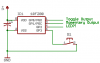
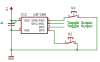
I forgot the correct name of the circuit, but I would like to integrate it into one of my upcoming robots. This is how it works:

You press a momentary button (not a tactile, where it depresses) and it turns on the circuit and keeps it on until you press the switch again. What is this called using a momentary switch? does this require a microcontroller?
 
There have been circuits posted for this in the past - including some by me. Do a search for "flip flop" or "toggle switch".
 
Thanks, I found one, and I happen to have all the stuff I need there... I think thats a first time ever!
 
Lol, I forgot to write down the site so that I could build it...

I am using a 74HC74. A link would be nice!
 
I got the circuit working, but I am having trouble with button debounce. any suggestions?
 
This circuit is simpler and works well. You can have 3 circuits from one IC or use the leftover inverters tin parallel to boost the current. The capacitor debounces the pushbutton.
 

Attachments

  • Alternate-action.gif
    Alternate-action.gif
    3.6 KB · Views: 522
Thanks. Ill test it out right now!

is 47nf a 0.047uf cap? Could I use a 0.1 uf cap?
 
It works amazingly well! The 0.1 cap is a perfect substitute. Thanks!
 
If you jab at the button very quickly and the supply voltage to the Cmos IC is at 3v which is its lowest allowed, then it might not switch when its capacitor is 0.1uF.
 
I built it with a 5v regulator, then hooked up a 2907A to switch a circuits connection from its negative connection to GND. Pictures up later
 
Ordinary Cmos doesn't need a voltage regulator. It works with a supply voltage from 3V to 18V.
 
Well, I was going to help you but audioguru seems to have sorted you out and I don't think I have anything useful to add other than an amusing story (if you have my sense of humour) about a recent application for this circuit.

I modified the side lights on my Land Rover some time ago with green LEDs to match the colour of the vehicle. Took her in for an MOT (that's a compulsory annual test of roadworthyness here in the UK) and she failed for the lights. They're not allowed to be green, they have to be white.

So I took her home, and pondered the situation. I quite like the green glow when the side lights are on and I didn't really want to have to put her back to the original spec. I could Take the green LEDs out, fit white for the MOT and then fit green back in there afterwards but that would be a bit of a drag so in the end I re-modified the light cluster with green AND white LEDs. I hooked them up to a circuit similar to the one AudioGuru has shown here, with a button installed into my dash marked "MOT button". The circuit is powered by constant 12V so it always remembers it's current state.

I took the Land Rover back in for the retest and the mechanic called me over. "These lights are still green!!!" he said. "Push the MOT button on the dash!" I replied, and left him to it. Needless to say she passed, and I drove out with green lights :D

Childish I know. But hey gotta be done every now and then!

Might think of some more things I can hook up to the MOT button actually. Hmmmm...

Brian
 
Last edited:
I wonder if you could have a MOT button to select the worn out old brake pads or select new pads to pass the test. Then you drive on the old brake pads until they are completely gone.
 
I don't mean to detract from AudioGuru's excellently simple circuit; but I'm a fan of every problem has a microcontroller solution.

Two different layout ideas for a simple, small and inexpensive toggle switch, using the small and inexpensive (USD 0.60) 10F200 chip from microchip. The chip can be programmed to be a simple on/off toggle, or more complex jobs like a time delay toggle (press and hold for N seconds to turn on), or whatever else you can cram in 384 bytes.

First idea is a single toggle that also has a momentary output and a status LED. Second idea is a dual toggle.

The '200 offers a wake on event interrupt for all its inputs, and also has internal pull-up resistors, reducing the part count and debounce is easily performed in software.
 

Attachments

  • toggle1.png
    toggle1.png
    2.3 KB · Views: 261
  • toggle2.png
    toggle2.png
    2.3 KB · Views: 325
Status
Not open for further replies.

New Articles From Microcontroller Tips

Back
Top