Electro Tech is an online community (with over 170,000 members) who enjoy talking about and building electronic circuits, projects and gadgets. To participate you need to register. Registration is free. Click here to register now.
Welcome to our site! Electro Tech is an online community (with over 170,000 members) who enjoy talking about and building electronic circuits, projects and gadgets. To participate you need to register. Registration is free. Click here to register now.
Can any one help me giving a flexible circuite, which swithchoff the AC Motor when the water in the over head tank is filled. This will help me in saving water from flowing from over head tank.
I know theirs a way to do this becuase my dad did it when we had two big 5,000 gal. tanks that stored water from the well.
He had two probes stuck inside the top of the tank. One was really long and the other was very short. When the water was high enough to hit both, the long probe and the short one, the pump went off. When the water was low enough so it didn't touch any of the two probes, the pump turned on. The probes where just long pieces of stiff wire.
I know that the water had 12 volts applied to it the whole time.
Sorry I can't be of any more assistance , I can't remember the rest of the circuit, but maybe you could build off this :?
All you need is a switch and a floating bouy, when the bouy floats up to the correct level, it hits the switch, which drops a relaly which kills the pump.
Like eblc1388 pointed out, there needs to be a means of preventing the pump switching on and off too frequently. I suggest fixing another switch arrangement to the underside of the bouy arrangement, so that only when that switch is activated will the motor switch back on. Seems like a counter circuit or at least some kind of simple logic will be required here.
Like eblc1388 pointed out, there needs to be a means of preventing the pump switching on and off too frequently. I suggest fixing another switch arrangement to the underside of the bouy arrangement, so that only when that switch is activated will the motor switch back on. Seems like a counter circuit or at least some kind of simple logic will be required here.
The switch and mechanics will provide a degree of hysteresis anyway, but the existing float systems in your house (water tanks, toilet etc.) don't require anything extra?.
Just like those, the output from the tank is likely to be greater than it's input - so as you start using water from the tank the float will drop, and the pump will turn ON. However, the pump is unlikely to replace the water in the tank faster than it's being emptied (or why have a storage tank?), so there won't be any pump cycling problems. Once the water being used from the tank is turned OFF, then the pump will simply keep going until it's refilled, then be turned OFF by the float switch.
Why try and get complicated, when there's most probably no reason?.
When I first arrived in Australia, I lived in a rental that didn't have mains water. Water was stored in a 20,000Ltr tank that was filled with rain water or, if it didn't rain, from a bore hole. The bore delivered about 1500Ltrs per hour and was about 30Mtrs below the storage tank (yes, it was a big pump). The output was definitely less than the input.
If this is the arrangement that the original poster has then a ball float is not the way to go and the 2 rod system above sounds like a good idea.
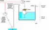
This is not really intended to be a practical arrangement, although
something similar probably could be practical.
It sort of popped into my mind when i saw the comments on simplicity
and complications.
I put it forward as a contender for the kiss prize.
The idea does not rely on friction. It relies on mechanical advantage.
If, ignoring the weight of the floats, weight 2 is 500g submerged and the displacement of the floats are 300g then the submerged weight and float on the left side is 200g, and weight 1 is 200g. In position 1 weight 1 has full mechanical advantage and the other side has (45°) 1/√2 advantage = 141g, so is stable. (Relative moments) The same reasoning applies to position 2. Using a single float that slides will work as long as it weighs enough to tip the balance at low level, in this example more than 59g and has enough spare displacement above this at the high level to lift more than 59g.
I suggest going to the following: Omega.com and reviewing the good reference material and products available for level control. I use their products for temp,level,pressure,flow,and data aquisition at my job all the time. They have float assemblies that can be mounted in the tank with various combinations of N.O., N.C. switches that can be used to turn a pump on to fill the tank and shut it off when it is full. A relay doesn't even have to be used when using two switches. The length of they bouy's magnet can control cycling. Of course, Hysterysis and cycling could also be controlled using a time delay relay. There are several other alternatives including capacitance and conductivity sensors that can also work.
another way to control level is with a pressure switch. Mount the switch at the bottom of the tank and adjust diaghram spring tension to tank head pressure level. deadband is introduced by the mechanical spring.
This site uses cookies to help personalise content, tailor your experience and to keep you logged in if you register.
By continuing to use this site, you are consenting to our use of cookies.

 , I can't remember the rest of the circuit, but maybe you could build off this :?