This circuit is a Digital Temerature Sensor using a Dallas '1-wire' DS18B20 Digital Thermometer
Firstly I would like to thank Pommie and Mike, K8LH from the Electro Tech Online Forum for their genourous help. This has been the most challenging project to date and they have helped immensely. They have tought me many valuable lessons about programming in Assembly language and it has really assitsted me in getting this project up and running.
Note: I would like to make a point that some snippets of their own code is used in this program. I have used it with their permission and please observe any copyrights or name recognition placed in the code. If you wish to use their snippets of code, please contact them via the Electro-Tech-Online forum.
How It Works
The DS18B20 is a direct-to-digital temperature sensor using Maxim's exclusive 1-Wire bus protocol that implements bus communication using one control signal. In regards to hardware, this particular sensor is particularly easy to interface to. It only requires 1 external pull-up resistor to operate as opposed to an analogue sensor which possibly needs multiple external components such as resistors and op-amps.
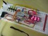
In regards to software, opposed to analogue sensors, the Dallas 1-wire digital sensors are arguably as easy to interface to. While an analogue sensor will need an Analogue to Digital conversion using a voltage reference and possibly using an op-amp, the Dallas 1-wire direct to digital sensors require precise timing when it comes to communication. This program is fairly basic in principle as all it does is obtain temperature data from the DS18B20 sensor and display the temperature in Degrees Celsius on a 4 digit, 7 segment display. But when it comes to actually doing this, as you will see from the .ASM file, it is more complicated than it sounds. In words; the program first initialises the PIC16F628A Microcontroller. It assigns the Inputs and Outputs, zero's all bank 0 RAM, initialises the display column select bit and configures TIMER 2. TIMER 2 is used to interrupt the normal loop of the program to update the 7 segment LED display.
After the Microcontroller has been setup, it begins communication with the DS18B20 Temperature Sensor. Communication routines take up just under half of the program memory. After the temperature has been gathered and stored in RAM, the Microcontroller takes the 12-bit signed/fraction integer and converts it into a decimal number then stores it in four general purpose registers in RAM.
For example, take the number D'95.8'. It is stored like this:
These registers are then used within the Interrupt Service Routine to call a table to obtain display data.
The program runs continuously, updating the temperature on the display just over once per 1 second.
Features Summary:
Video
[video=youtube;BgGgik1DgQs]http://www.youtube.com/watch?v=BgGgik1DgQs[/video]
Parts List
Firstly I would like to thank Pommie and Mike, K8LH from the Electro Tech Online Forum for their genourous help. This has been the most challenging project to date and they have helped immensely. They have tought me many valuable lessons about programming in Assembly language and it has really assitsted me in getting this project up and running.
Note: I would like to make a point that some snippets of their own code is used in this program. I have used it with their permission and please observe any copyrights or name recognition placed in the code. If you wish to use their snippets of code, please contact them via the Electro-Tech-Online forum.
How It Works
The DS18B20 is a direct-to-digital temperature sensor using Maxim's exclusive 1-Wire bus protocol that implements bus communication using one control signal. In regards to hardware, this particular sensor is particularly easy to interface to. It only requires 1 external pull-up resistor to operate as opposed to an analogue sensor which possibly needs multiple external components such as resistors and op-amps.
In regards to software, opposed to analogue sensors, the Dallas 1-wire digital sensors are arguably as easy to interface to. While an analogue sensor will need an Analogue to Digital conversion using a voltage reference and possibly using an op-amp, the Dallas 1-wire direct to digital sensors require precise timing when it comes to communication. This program is fairly basic in principle as all it does is obtain temperature data from the DS18B20 sensor and display the temperature in Degrees Celsius on a 4 digit, 7 segment display. But when it comes to actually doing this, as you will see from the .ASM file, it is more complicated than it sounds. In words; the program first initialises the PIC16F628A Microcontroller. It assigns the Inputs and Outputs, zero's all bank 0 RAM, initialises the display column select bit and configures TIMER 2. TIMER 2 is used to interrupt the normal loop of the program to update the 7 segment LED display.
After the Microcontroller has been setup, it begins communication with the DS18B20 Temperature Sensor. Communication routines take up just under half of the program memory. After the temperature has been gathered and stored in RAM, the Microcontroller takes the 12-bit signed/fraction integer and converts it into a decimal number then stores it in four general purpose registers in RAM.
For example, take the number D'95.8'. It is stored like this:
Code:
HUNS register = 0
TENS register = 9
ONES register = 5
TENTHS register = 8
These registers are then used within the Interrupt Service Routine to call a table to obtain display data.
The program runs continuously, updating the temperature on the display just over once per 1 second.
Features Summary:
- Temperature data gathered more than once per second.
- TIMER 2 interrupt driven display.
- Program expandable to include multiple sensors on the same 1-Wire bus.
- Temperature range of -55.0 - 127.9 Degrees Celsius.
Video
[video=youtube;BgGgik1DgQs]http://www.youtube.com/watch?v=BgGgik1DgQs[/video]
Parts List
| Quantity | Schematic Designator | |
| Semiconductors | ||
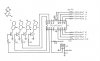
| Dallas DS18B20 Digital Temperature Sensor | 1 | U2 |
| PIC16F628A (can use 627A or 648A) | 1 | U1 |
| LED 7 Segment (Common Cathode) | 4 | D1 - D4 |
| BC548 NPN Transistor | 4 | Q1 - Q4 |
| Resistors | ||
| 330Ω | 1 | R12 |
| 470Ω | 7 | R5 - R11 |
| 4.7KΩ | 1 | R13 |
| 10KΩ | 4 | R1 - R4 |
| Capacitors | ||
| .1μF Multilayer Ceramic | 2 | C1 - C2 |
| Hardware | ||
| Breadboard | 1 | |
| Jumper Wires | Numerous |