A lot of times when building circuits, (such as op-amp circuits), you'll find that you need a power supply with both positive(+) and negative(-) rails, in addition to a common ground(gnd). It is easy enough to connect two batteries or two wall adapters together and use the center connection for your ground, but there are some problems with this. What if one battery goes dead faster than the other? What if you can't have or don't want two wall adapters hanging off the wall? What if you can't find or afford two of anything? What if you want a fairly exact split in voltage?
If the above are problems for you, and you need something a bit better, then the following circuit is the answer you seek. It can be used in low-medium power designs when you want to get positive and negative power out of a single battery or wall adapter.

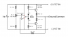
Notes:
Most parts are substitutable, just mirror the top and bottom half.
Resistor R4 *ONLY* connects to ground/common and - of the op-amp.
The red dots are the power pins for the op-amp IC.
Vin can be any source or any voltage up to ~32V
If you only need a few mA, you can remove R5-R8 and D1-D2 and Q1-Q2.
R7 and R8 are not strictly needed, but should be 10 Ohm, 1W ceramic resistors.
Warnings
Q1-Q2 and R7-R8 can get hot under high load. Heat sinking Q1-Q2 is preferred.
Q1 and Q2 should be complementary pairs. (TIP31 and TIP32 for example)
Current that can be supplied is limited by Q1-Q2.
Output voltages will drop if too much current is drawn.
Output voltages will likely drift with temperature changes. (Not tested)
This circuit is electrically inefficient. Not recommended for portables.
Be very careful about power supply decoupling. This circuit *CAN* oscillate with bad configurations.
DON'T PM ME LOOKING FOR PERSONAL HELP BUILDING THIS. USE THE FORUMS.
I'M NOT RESPONSIBLE FOR ANYTHING RELATED TO YOU BUILDING OR USING THIS.
-()blivion
If the above are problems for you, and you need something a bit better, then the following circuit is the answer you seek. It can be used in low-medium power designs when you want to get positive and negative power out of a single battery or wall adapter.
Notes:
Most parts are substitutable, just mirror the top and bottom half.
Resistor R4 *ONLY* connects to ground/common and - of the op-amp.
The red dots are the power pins for the op-amp IC.
Vin can be any source or any voltage up to ~32V
If you only need a few mA, you can remove R5-R8 and D1-D2 and Q1-Q2.
R7 and R8 are not strictly needed, but should be 10 Ohm, 1W ceramic resistors.
Warnings
Q1-Q2 and R7-R8 can get hot under high load. Heat sinking Q1-Q2 is preferred.
Q1 and Q2 should be complementary pairs. (TIP31 and TIP32 for example)
Current that can be supplied is limited by Q1-Q2.
Output voltages will drop if too much current is drawn.
Output voltages will likely drift with temperature changes. (Not tested)
This circuit is electrically inefficient. Not recommended for portables.
Be very careful about power supply decoupling. This circuit *CAN* oscillate with bad configurations.
DON'T PM ME LOOKING FOR PERSONAL HELP BUILDING THIS. USE THE FORUMS.
I'M NOT RESPONSIBLE FOR ANYTHING RELATED TO YOU BUILDING OR USING THIS.
-()blivion