Charging a capacitor by switching a DC voltage source means only 1/2 the energy is stored on the capacitor.
The other half of the energy is dissipated as heat in the source and switch resistance. It makes no difference how low the resistance, half the energy will be lost.
To minimize this loss, a resonant charging technique can be used. which will transfer most of the energy to the capacitor, minus only a smaller loss in the diode, and the inductor & source stray resistances.
This will also charge the capacitor to near double the source voltage, which is a fourfold increase in stored energy (½CV²).
The reason the inductive method is more efficient, even with the same source resistance, is that the inductor losslessly reduces the peak charging current by storing some of the energy (½LI²) during the first half of the charge process and then discharging this energy into the capacitor after the capacitor voltage exceeds the source voltage. The larger the inductor, the lower the peak current.
Since the resistive loss is proportional to the square of the current (I²R), the lower the peak current, the smaller the total resistive dissipation for a given charge quantity transferred through the resistance into the capacitor.
The resonant charging is performed by simply placing a small inductor and diode in series with the source.
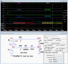
The LTspice simulation below shows the difference in stored energy between resistive charging and inductive charging.
E1 is a VCVS (voltage controlled voltage source) that mirrors the voltage from V1.
Rs is the simulated source/switch resistance.
The diode is required in the inductive charge circuit to capture the peak resonant voltage on the capacitor. A Schottky is used for better charge efficiency.
If a MOSFET synchronous switch were used instead of the diode, even higher charge efficiency could be achieved.
The input to both is a 10V pulse, simulating the closing of a switch.
The voltage on C1 is 10V at the end of the charge as expected.
The voltage on C2 at the end is ≈18.5V, showing the voltage (and energy) gained by inductive charging.
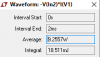
The energy stored in the capacitors is shown in graphs 3 and 4.
The energy at the end of the charge is shown in the top measurement box.
It's 5.0mJ for C1 and 17.1mJ for C2
The power generated by the two sources in shown in graphs 2 and 3.
The total energy over the interval is shown for E1 in the 2nd box as 9.90mJ.
The total energy for V1 is shown in the 3rd box as 18.5mJ.
The efficiency for resistance charging is then 5.0mJ / 9.90mJ = 50.5% (approximately as expected).
The efficiency for inductive charging is 17.1mJ / 18.5mJ = 92.4%.
Thus the inductive charge is about 1.83 times as efficient as resistive charging, for the simulated conditions.
The capacitor charge time for the inductive circuit is approximately 1/2 cycle of the LC resonant frequency or π√(LC).
Thus for the simulated values of 1mH and 100μF, the charge time is π√(1mH*100μF) ≈0.993ms, which is very close to the simulated value of 1.01ms.
A lower inductance would give less efficient, but faster charging while a larger inductance would give more efficient but slower charging time.
This efficiency change occurs because the the peak resonant current is inversely proportional to inductor size, which changes I²R losses from the parasitic series resistances, as previously noted.
The tradeoffs are charge efficiency vs charge time and physical inductor size and cost.

---------------------------------------------------------------

The other half of the energy is dissipated as heat in the source and switch resistance. It makes no difference how low the resistance, half the energy will be lost.
To minimize this loss, a resonant charging technique can be used. which will transfer most of the energy to the capacitor, minus only a smaller loss in the diode, and the inductor & source stray resistances.
This will also charge the capacitor to near double the source voltage, which is a fourfold increase in stored energy (½CV²).
The reason the inductive method is more efficient, even with the same source resistance, is that the inductor losslessly reduces the peak charging current by storing some of the energy (½LI²) during the first half of the charge process and then discharging this energy into the capacitor after the capacitor voltage exceeds the source voltage. The larger the inductor, the lower the peak current.
Since the resistive loss is proportional to the square of the current (I²R), the lower the peak current, the smaller the total resistive dissipation for a given charge quantity transferred through the resistance into the capacitor.
The resonant charging is performed by simply placing a small inductor and diode in series with the source.
The LTspice simulation below shows the difference in stored energy between resistive charging and inductive charging.
E1 is a VCVS (voltage controlled voltage source) that mirrors the voltage from V1.
Rs is the simulated source/switch resistance.
The diode is required in the inductive charge circuit to capture the peak resonant voltage on the capacitor. A Schottky is used for better charge efficiency.
If a MOSFET synchronous switch were used instead of the diode, even higher charge efficiency could be achieved.
The input to both is a 10V pulse, simulating the closing of a switch.
The voltage on C1 is 10V at the end of the charge as expected.
The voltage on C2 at the end is ≈18.5V, showing the voltage (and energy) gained by inductive charging.
The energy stored in the capacitors is shown in graphs 3 and 4.
The energy at the end of the charge is shown in the top measurement box.
It's 5.0mJ for C1 and 17.1mJ for C2
The power generated by the two sources in shown in graphs 2 and 3.
The total energy over the interval is shown for E1 in the 2nd box as 9.90mJ.
The total energy for V1 is shown in the 3rd box as 18.5mJ.
The efficiency for resistance charging is then 5.0mJ / 9.90mJ = 50.5% (approximately as expected).
The efficiency for inductive charging is 17.1mJ / 18.5mJ = 92.4%.
Thus the inductive charge is about 1.83 times as efficient as resistive charging, for the simulated conditions.
The capacitor charge time for the inductive circuit is approximately 1/2 cycle of the LC resonant frequency or π√(LC).
Thus for the simulated values of 1mH and 100μF, the charge time is π√(1mH*100μF) ≈0.993ms, which is very close to the simulated value of 1.01ms.
A lower inductance would give less efficient, but faster charging while a larger inductance would give more efficient but slower charging time.
This efficiency change occurs because the the peak resonant current is inversely proportional to inductor size, which changes I²R losses from the parasitic series resistances, as previously noted.
The tradeoffs are charge efficiency vs charge time and physical inductor size and cost.
---------------------------------------------------------------