Issue: Draft 03 of 2016_11_203
INTRODUCTION
It is important that most rechargeable batteries are not discharged lower than a specified cell voltage. This is especially true of Lithium Ion (LiIon) batteries which may be damaged by too-lower cell voltage.
This article describes a simple, low-cost, flexible circuit, that can be adjusted to suit most cut off voltages. The circuit also has hysteresis which caters for battery rebound and prevents the circuit from oscillating on and off.
As the circuit uses a floating comparator and voltage reference, the only practical limit on the maximum operating voltage is imposed by the voltage max Drain/Source of the PMOSFET.
One of the challenges of a cut-off circuit is to ensure that the static current consumption is less than the self discharge current of the battery being monitored. The other challenge is to make the circuit as unobtrusive as possible, the main factor being the resistance of the power switch to turn the battery on and off. In order to keep the resistance low a power PMOSFET is employed as the switch.
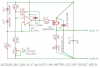
Below is a precision battery cut-off circuit that has been configured for 48V nominal cut-off voltage.
(1) Change LED to type Vishay TLLK4401
CIRCUIT OPERATION
(1) The cut-off voltage can be set from 46V to 50V by adjusting RV3. This range can be changed if required.
(2) The LED illuminates when the PMOSFET is turned on. The LED can be removed if not required but it is advisable to still have a 47K resistor connected from the PMOSFET drain to 0V.
PERFORMANCE
(1) This is a precision circuit and will have negligible voltage drift (at a guess Vcoff +-10mV from 10 Deg C to 50 Deg C)
(2) The current consumption of the circuit is 48uA (micro Amps) when cut off. This could be reduced. The current consumption will be essentially the same when cut on, except for the additional LED current of 1mA.
(3) The hysteresis is presently set to 10% so, if the cut off voltage were set to 48V, the circuit would not cut on until the battery voltage had increased to 52.8V. The hysteresis can be altered by changing the value of R18
(4) The circuit will switch 5A easily.
CONSTRUCTION
(1) The LED is a high efficiency type (2mA current). The LED brightness can be increased by reducing the value of R19
(2) This is a low current, high impedance circuit so the physical layout is critical.
(3) This is a low current, high impedance circuit, so it will need to be protected from contaminates, especially condensation. A varnish conformal coating may even be required, depending on the environment.
(4) This is a low current, high impedance circuit and is susceptible to electromagnetic interference (EMI) so it should not be place in electrostatic or magnetic fields. A metal screening case is advisable.
(5) A snubbing diode is not required for protection to switch inductive loads (relay) because the PMOSFET has a built-in diode that will do the job.
(6) The physical layout must be as shown in the schematic, with special reference to the battery and PMOSFET. Heavy schematic lines indicate heavy wire or printed circuit traces.
(7) R14 is a gate stopper to reduce the chance of the PMOSFET oscillating. R14 also isolates the output of the opamp from the large effective input capacitance of the PMOSFET gate.
COMPONENTS
(1) The schematic shows the pin numbering for the TLV3701ID (SOIC-8 package)
(2) All resistors, unless otherwise stated (UOS), are metal oxide, 0.250W or more, 5%, or better, thru hole (not surface mount).
(3) RV3 is a multi-turn potentiometer and may not be available in metal oxide (to be advised)
(4) All capacitors are ceramic X7R dielectric UOS, +- 10%, or better. C5 is 10V working minimum. C6 is 60V working minimum. It may be necessary to parallel a number of capacitors to achieve C6 value. C6 can be polypropylene dialectic. Do not be tempted to omit these decoupling capacitors- they are essential for the frequency stability of the circuit.
DATASHEETS
http://www.ti.com/lit/ds/symlink/tlv3701.pdf
https://datasheets.maximintegrated.com/en/ds/MAX6006A-MAX6009B.pdf
http://www.vishay.com/docs/62971/sqm100p06-9m3l.pdf
http://www.vishay.com/docs/83343/tlle4401.pdf