In the past when requiring to monitor I2C communications between two devices I would use a logic analyzer. Such monitoring was useful to determine if the I2C communications between devices was properly configured. Even though this is quite useful and efficient, it does require a logic analyzer, with an I2C protocol debugger. Such devices are actually pretty common and not too expensive (e.g. Saleae Logic analyzer), but sometimes these may be overkill and a small specialized device may suffice. In comes the I2C monitor. Something which:
This is nothing new, in fact the ideas behind this project were born from the following projects:
DESIGN
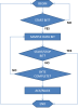
To monitor simple I2C communications between two or more devices and output these transactions through RS232 to a PC, in some of the reference designs listed before most of the work is done by the MCU. The MCU samples the SCL and SDA lines and has to determine the START and STOP conditions, as well as the normal data. The flow diagram sort of goes as follows:

To help the MCU keep up with the data, external hardware is added to handle the Start and Stop conditions. This was done on both the "I2C Bus Sniffer on AVR" and "The Secrets of I2C" articles; as well as article "Robust I2C Slave Without a Sampling Clock". Such implementation requires four dedicated pins: three interrupt pins (one for Start condition, one for Stop condition, one for SCL), and one standard input for SDA. In addition the MCU requires built-in USART hardware.
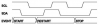
The next figure provide illustration of how create the two additional hardware blocks for the Start and Stop conditions needed. During normal transactions the SDA (data) line is only allowed to change when the SCL (clock) line is at a logic low. A Start and Stop condition is then defined by a change of the SDA line when the SCL line is at a logic high; the Start condition indicated when the SDA transfers from at a logic high to a at a logic low with the SCL at a logic high, and the Stop condition indicated when the SDA transfers from at a logic low to a at a logic high with the SCL at a logic high.

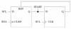
Flip-Flops can be used to create a simple method to identify these conditions, and create simple pulses to indicate either condition. The next figure shows a dual D-type flip-flop configuration used to determine a Start condition.

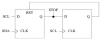
The following figure, on the other hand, shows a dual D-type flip-flop configuration used to determine the Stop condition.

These Flip-Flop hardware blocks together with the MCU can now provide the building blocks for the I2C monitor. The I2C Start command, as decoded by the flip-flop, can trigger an I/O interrupt on the MCU indicating the start of the message. The I2C Stop command, as decoded by the flip-flop, can trigger a separate I/O interrupt on the MCU indicating the end of the message.
For proper operation, the following requirements exist for the MCU:
For the implementation Microchip’s 18F1320 PIC was chosen. This MCU has the following specifications:
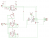
IMPLEMENTATION
The following figure shows the implementation of the proposed design. For a quick prototype, the FTDI interface was replaced with an FTDI TTL cable. Oshonsoft Basic was used to code and simulate the PIC MCU operation before actual implementation and testing of the hardware. The prototype worked as expected with two caveats: (1) the maximum bus supported speed is 100kHz, and (2) if the internal buffer on the MCU overflows there is currently no indication for this. Ideally such a device would work for I2C communications up to 400kHz, but this is limited by the PIC MCU clock and the RS232 output routines. The higher I2C communications are better suited for an FPGA implementation.

- can monitor simple I2C communications between two or more devices (at up to 100kHz bus speeds)
- does not respond, acknowledge, or in any way modify the communication being monitored
- outputs the transactions through RS232
This is nothing new, in fact the ideas behind this project were born from the following projects:
- Design Note 48 (I2C Bus Sniffer)
- I2C Bus Sniffer on AVR
- The Secrets of I2C - An I2C bus analyser to let you satisfy your curiosity
DESIGN
To monitor simple I2C communications between two or more devices and output these transactions through RS232 to a PC, in some of the reference designs listed before most of the work is done by the MCU. The MCU samples the SCL and SDA lines and has to determine the START and STOP conditions, as well as the normal data. The flow diagram sort of goes as follows:
To help the MCU keep up with the data, external hardware is added to handle the Start and Stop conditions. This was done on both the "I2C Bus Sniffer on AVR" and "The Secrets of I2C" articles; as well as article "Robust I2C Slave Without a Sampling Clock". Such implementation requires four dedicated pins: three interrupt pins (one for Start condition, one for Stop condition, one for SCL), and one standard input for SDA. In addition the MCU requires built-in USART hardware.
The next figure provide illustration of how create the two additional hardware blocks for the Start and Stop conditions needed. During normal transactions the SDA (data) line is only allowed to change when the SCL (clock) line is at a logic low. A Start and Stop condition is then defined by a change of the SDA line when the SCL line is at a logic high; the Start condition indicated when the SDA transfers from at a logic high to a at a logic low with the SCL at a logic high, and the Stop condition indicated when the SDA transfers from at a logic low to a at a logic high with the SCL at a logic high.
Flip-Flops can be used to create a simple method to identify these conditions, and create simple pulses to indicate either condition. The next figure shows a dual D-type flip-flop configuration used to determine a Start condition.
The following figure, on the other hand, shows a dual D-type flip-flop configuration used to determine the Stop condition.
These Flip-Flop hardware blocks together with the MCU can now provide the building blocks for the I2C monitor. The I2C Start command, as decoded by the flip-flop, can trigger an I/O interrupt on the MCU indicating the start of the message. The I2C Stop command, as decoded by the flip-flop, can trigger a separate I/O interrupt on the MCU indicating the end of the message.
For proper operation, the following requirements exist for the MCU:
- MCU must be clocked at the highest MHz rate possible (this is to be able to keep up with high data rates during the interrupt routines)
- MCU requires dedicated USART hardware/pins
- MCU requires three interrupt pins
For the implementation Microchip’s 18F1320 PIC was chosen. This MCU has the following specifications:
- 40MHz clock (10MHz internal – using x4 PLL)
- Two dedicated USART pins
- Four dedicated interrupt pins (one is shared with USART, so CCP pin is used as third)
IMPLEMENTATION
The following figure shows the implementation of the proposed design. For a quick prototype, the FTDI interface was replaced with an FTDI TTL cable. Oshonsoft Basic was used to code and simulate the PIC MCU operation before actual implementation and testing of the hardware. The prototype worked as expected with two caveats: (1) the maximum bus supported speed is 100kHz, and (2) if the internal buffer on the MCU overflows there is currently no indication for this. Ideally such a device would work for I2C communications up to 400kHz, but this is limited by the PIC MCU clock and the RS232 output routines. The higher I2C communications are better suited for an FPGA implementation.
Code:
'Author: languer (©2012)
'Pin Allocation:
'PIN# Main_Fn                 Secondary_Fn
'RA0 -> not used
'RA1 -> not used
'RA2 -> not used
'RA3 -> not used
'RA4 -> not used
'RA5 -> MCLR
'RA6 -> OSC
'RA7 -> OSC
'RB0 -> I2C START Interrupt
'RB1 -> TX_RS232 (PC_RX)
'RB2 -> I2C STOP Interrupt
'RB3 -> I2C SCL Interrupt (using CCP)
'RB4 -> RX_RS232 (PC_TX)
'RB5 -> not used
'RB6 -> I2C SDA               PGC (Programming clock)
'RB7 -> CTS#                  PGD (Programming data)
'Usage Information:
'RS232 Baud Rate: 115.2kbps
'Version Info:
'rs232 comms on array at main loop
'max speed is 100kHz
'no indication if buffer overflows

'General Configuration
'for external 10MHz w PLL (40MHz)
Define CONFIG1L = 0x00
Define CONFIG1H = 0x06
Define CONFIG2L = 0x0a
Define CONFIG2H = 0x00
Define CONFIG3L = 0x00
Define CONFIG3H = 0x80
Define CONFIG4L = 0x80
Define CONFIG4H = 0x00
Define CONFIG5L = 0x03
Define CONFIG5H = 0xc0
Define CONFIG6L = 0x03
Define CONFIG6H = 0xe0
Define CONFIG7L = 0x03
Define CONFIG7H = 0x40

'Oscillator/Clock Configuration
Define CLOCK_FREQUENCY = 40

'HW UART Setup
Hseropen 115200

'RS232 Definitions
Symbol io_rs232tx = RB1  'mcu rs-232 output
Symbol io_rs232rx = RB4  'mcu rs-232 input
Symbol io_rs232ctsn = RB7  'mcu rs232 cts# handshake signal

'I2C Definitions
Symbol io_i2cstart = RB0
Symbol io_i2cstop = RB2
Symbol io_i2cscl = RB3
Symbol io_i2csda = RB6

'Constants
Const trisa1 = %11111111
Const trisb1 = %01111101
Dim _true As Bit
Dim _false As Bit
_true = True
_false = False

'Variables
Dim flag_i2cstart As Bit
Dim flag_i2cstop As Bit
Dim i2cack As Byte
Dim i2cdata As Byte
Const i2cbuffersize = 200
Dim i2carray(200) As Byte
Dim i2cnextin As Byte
Dim i2cnextout As Byte
Dim bitcount As Byte

'Main Program
main:
WaitMs 2500
Call init()

'enable interrupt routines
INTCON.INT0IE = True  'enable RB0/I2CSTART interrupt
CCP1CON = %00000101  'enable RB3/CCP1/I2CSCL
Enable High  'enable general interrupt

Dim data As Byte
Dim cnt As Byte
While _true
If i2cnextout = i2cnextin Then
'do nothing
Else
'loop-around buffer
If i2cnextout = i2cbuffersize Then
i2cnextout = 0
Endif
'hserout when TXREG is empty
If PIR1.TXIF = True Then
data = i2carray(i2cnextout)
TXREG = data
i2cnextout = i2cnextout + 1
Endif
Endif
Wend
End

Proc init()
AllDigital
TRISA = trisa1
TRISB = trisb1

flag_i2cstart = False
flag_i2cstop = False
i2cack = 0
i2cdata = 255
i2cnextin = 0
i2cnextout = 0
bitcount = 0

'Hserout "Start...", CrLf
End Proc

On High Interrupt
Dim hex1 As Byte
Dim hex2 As Byte

'START/RESTART Condition (3.6us / 29Tcy)
If INTCON.INT0IF = True Then  'RB0/I2CSTART flag
INTCON.INT0IF = False  'RB0/I2CSTART flag
INTCON3.INT2IF = False  'RB2/I2CSTOP flag
INTCON3.INT2IE = True  'enable RB2/I2CSTOP interrupt
flag_i2cstop = False
bitcount = 0
PIR1.CCP1IF = False  'RB3/CCP/I2CSCL  flag
PIE1.CCP1IE = True  'enable RB3/CCP/I2CSCL interrupt
INTCON.PEIE = True  'enable peripheral interrupt (required for RB3/CCP/I2CSCL)
'loop-around buffer
If i2cnextin = i2cbuffersize Then
i2cnextin = 0
Endif
If flag_i2cstart = True Then
i2carray(i2cnextin) = "R"  'restart condition"
Else
flag_i2cstart = True
i2carray(i2cnextin) = "S"  'start condition
Endif
i2cnextin = i2cnextin + 1
Endif

'STOP Condition (3.0us / 24Tcy)
If INTCON3.INT2IF = True Then  'RB2/I2CSTOP flag
INTCON3.INT2IE = False  'disable RB2/I2CSTOP interrupt
INTCON3.INT2IF = False  'RB2/I2CSTOP flag
INTCON.PEIE = False  'disable peripheral interrupt (required for RB3/CCP/I2CSCL)
PIE1.CCP1IE = False  'disable RB3/CCP/I2CSCL interrupt
PIR1.CCP1IF = False  'RB3/CCP/I2CSCL flag
flag_i2cstart = False
'loop-around buffer
If i2cnextin = i2cbuffersize Then
i2cnextin = 0
Endif
i2carray(i2cnextin) = "P"  'stop condition
i2cnextin = i2cnextin + 1
Endif

'DATA Condition
'(2.4us / 18Tcy for Bits 0-6)
'(7.2us / 55Tcy for Bit 7)
'(7.4us / 58Tcy for ACK/NACK)
If PIR1.CCP1IF = True Then  'RB3/CCP/I2CSCL flag
PIR1.CCP1IF = False  'RB3/CCP/I2CSCL flag
Select Case bitcount
Case < 7
'shift data left and add new i2cdata bit
'i2cdata = ShiftLeft(i2cdata, 1)
ASM:        RLCF i2cdata,1
If io_i2csda = True Then  'add
i2cdata = i2cdata + 1
Endif
bitcount = bitcount + 1
Case 7
'shift data left and add last i2cdata bit
'i2cdata = ShiftLeft(i2cdata, 1)
ASM:        RLCF i2cdata,1
If io_i2csda = True Then  'add
i2cdata = i2cdata + 1
Endif
bitcount = bitcount + 1
'store I2CDATA
'loop-around buffer
'hex1 = ShiftRight(i2cdata, 4)
ASM:        movff i2cdata,hex1
ASM:        movf hex1,w
ASM:        andlw 0xf0
ASM:        movwf hex1
ASM:        RRNCF hex1,1
ASM:        RRNCF hex1,1
ASM:        RRNCF hex1,1
ASM:        RRNCF hex1,1
hex1 = LookUp("0123456789ABDCEF"), hex1
'hex2 = i2cdata And 0x0f
ASM:        movff i2cdata,hex2
ASM:        movlw 0x0f
ASM:        andwf hex2,1
hex2 = LookUp("0123456789ABDCEF"), hex2
Case Else
'ACK/NACK bit
If i2cnextin = i2cbuffersize Then
i2cnextin = 0
Endif
i2carray(i2cnextin) = hex1
i2cnextin = i2cnextin + 1
If i2cnextin = i2cbuffersize Then
i2cnextin = 0
Endif
i2carray(i2cnextin) = hex2
i2cnextin = i2cnextin + 1

bitcount = 0

'store ack/nack STATUS
If io_i2csda = True Then  'test for ACK/NACK
i2cack = "A"
Else
i2cack = "N"
Endif
'loop - around buffer
If i2cnextin = i2cbuffersize Then
i2cnextin = 0
Endif
i2carray(i2cnextin) = i2cack
i2cnextin = i2cnextin + 1

EndSelect
Endif

Resume-
 i2c program flow.png
 -
 i2c communication example.png
 -
 i2c start detector.png
 -
 i2c stop detector.png
 -
 i2c monitor.png
