My sister and wife are in education, and the kids play a "Jeopardy" like game in the classroom. I wanted to make a circuit for them to use. After seeing several threads regarding game show circuits and attempting (unsuccessfully) to simulate many of them. I decided to attempt my own.
My circuit is for four players, and once anyone had pressed his/her button, their LED will illuminate and the circuit will lockout from any other inputs.
I used a 4013 D-type flip flop with the clock connected to a pushbutton input (more on this in the next paragraph) They clock on the rising edge. The D input is tied high, so that starting from a reset state (Q is low; Q' is high), the Q output will go high on a rising edge. The Reset inputs are held low with a pulldown resistor, and will reset when the input is brought high.
Locking out other players when one button is pressed is done by first sending the clock input through an dual input AND gate. The second input of this gate for each player is tied to the output of a quad input AND gate, whose inputs are driven through Q' from each flip flop. Thus, when one player buzzes in, his Q' will go low, all the AND gates will prevent input to any clock, thus effectively locking everyone from changing the state.
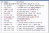
The parts I used are listed below, including part numbers from Digikey. What's missing from this list are some 6" servo extender cables that I had on hand.

Attachments are included to show the schematics.
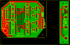
The board layout for creating the PCB is below. There is also attached a picture of an improved layout I developed.


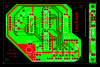
I developed an alternative layout, but the device was not constructed using this PCB. I use a 4k7 ohm SIP resistor to save layout space, and the trace routing is more orthagonal to make it easier to read and wire.

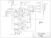
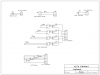
The schematic for this circuit is shown in two parts. The first is the supporting circuitry for the device. It was created using ExpressSCH.

The actual logic circuit schematic follows.

The attached .zip file contains the ExpressPCB schematic and PCB files.
My circuit is for four players, and once anyone had pressed his/her button, their LED will illuminate and the circuit will lockout from any other inputs.
I used a 4013 D-type flip flop with the clock connected to a pushbutton input (more on this in the next paragraph) They clock on the rising edge. The D input is tied high, so that starting from a reset state (Q is low; Q' is high), the Q output will go high on a rising edge. The Reset inputs are held low with a pulldown resistor, and will reset when the input is brought high.
Locking out other players when one button is pressed is done by first sending the clock input through an dual input AND gate. The second input of this gate for each player is tied to the output of a quad input AND gate, whose inputs are driven through Q' from each flip flop. Thus, when one player buzzes in, his Q' will go low, all the AND gates will prevent input to any clock, thus effectively locking everyone from changing the state.
The parts I used are listed below, including part numbers from Digikey. What's missing from this list are some 6" servo extender cables that I had on hand.
Attachments are included to show the schematics.
The board layout for creating the PCB is below. There is also attached a picture of an improved layout I developed.
I developed an alternative layout, but the device was not constructed using this PCB. I use a 4k7 ohm SIP resistor to save layout space, and the trace routing is more orthagonal to make it easier to read and wire.
The schematic for this circuit is shown in two parts. The first is the supporting circuitry for the device. It was created using ExpressSCH.
The actual logic circuit schematic follows.
The attached .zip file contains the ExpressPCB schematic and PCB files.
-
Lockout.zip
-
 upload_2014-6-26_22-2-30.png
 -
 upload_2014-6-27_9-9-22.png
 -
 Lockout-pcb_sm.png
 -
 lockout-sch_1.png
 -
 lockout-sch_2.png
