A simple MOSFET bridge rectifier can provide much lower forward drop than a standard or Schottky diode bridge for resistive loads, such as powering DC motors or plating baths from an AC source, where steady DC is not required.
This makes for higher efficiency and often no bridge heatsinking requirement, even for relatively high bridge currents.
It also can be used to provide the correct input DC power polarity to an electronic circuit for either polarity of the applied voltage, with very little voltage drop in either direction, thus eliminating any concern about incorrectly applied voltage polarity.
The bridge consists simply of two N-MOSFETs and two P-MOSFETs cross coupled so that their gates turn on at the proper time in the waveform.
---------------------------------------------------------------------------------------------------------------------------
As Bridge Rectifier---
During the low voltage part of the waveform, below their Vgs threshold voltages, the current is carried by their substrate diodes.
Thus for best efficiency, low Vgs(th) (logic-level) MOSFETs should be used.
Note that the bridge current direction is opposite the normal MOSFET drain-source direction, but that works since MOSFETs conduct equally well in either direction when ON.
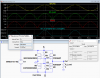
Below is the LTspice simulation of the bridge.

The voltage drop through the bridge is only about 100mV at a 7.5A peak current for the selected MOSFETs, with an average dissipation of about 100mW for each MOSFET.
The selected MOSFETs must be properly rated for the peak AC voltage you will use, with an ON resistance low enough so that the MOSFETs don't require a heat sink at the maximum load current, if feasible.
And as previously noted, low Vgs(th) devices will be slightly more efficient.
Dual and Quad MOSFETs are available with one/two N-MOSFETs and one/two P-MOSFETs in each package which can be used to reduce the parts count.
If the AC peak voltage is near or above the Vgs maximum rating of the MOSFETs, then an additional resistor must be added from each gate to ground with a value such that the resulting voltage divider will keep the peak Vgs below its rating.
Note that this simple circuit will not work with a capacitive load, such as for a DC supply, since the capacitor charge will leak back through the MOSFET when the AC voltage drops below the capacitor voltage.
For that you can use a circuit that includes comparators to turn off the MOSFET and prevent the capacitor discharge, such as discussed here.
-------------------------------------------------------------------------------------------------------------------------
As Polarity Protector---
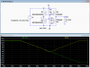
Below is a simulation showing the bridge providing a positive polarity to the load as the input goes from +15V to -15V.
The drop from the bridge input to output is less than 100mV @ 7.5A current.
The glitch in output voltage below 3V is where the MOSFETs turn off as the voltage becomes less than the MOSFET's Vgs threshold voltage and the body diodes start carrying the current.
So it can be seen that this circuit allows the power input connector to be non-polarized, and the circuit being powered will work equally well with either polarity input.
For voltages below 10V, logic-level type MOSFETs must be used with their Rds(on) specified at the power supply voltage.

This makes for higher efficiency and often no bridge heatsinking requirement, even for relatively high bridge currents.
It also can be used to provide the correct input DC power polarity to an electronic circuit for either polarity of the applied voltage, with very little voltage drop in either direction, thus eliminating any concern about incorrectly applied voltage polarity.
The bridge consists simply of two N-MOSFETs and two P-MOSFETs cross coupled so that their gates turn on at the proper time in the waveform.
---------------------------------------------------------------------------------------------------------------------------
As Bridge Rectifier---
During the low voltage part of the waveform, below their Vgs threshold voltages, the current is carried by their substrate diodes.
Thus for best efficiency, low Vgs(th) (logic-level) MOSFETs should be used.
Note that the bridge current direction is opposite the normal MOSFET drain-source direction, but that works since MOSFETs conduct equally well in either direction when ON.
Below is the LTspice simulation of the bridge.
The voltage drop through the bridge is only about 100mV at a 7.5A peak current for the selected MOSFETs, with an average dissipation of about 100mW for each MOSFET.
The selected MOSFETs must be properly rated for the peak AC voltage you will use, with an ON resistance low enough so that the MOSFETs don't require a heat sink at the maximum load current, if feasible.
And as previously noted, low Vgs(th) devices will be slightly more efficient.
Dual and Quad MOSFETs are available with one/two N-MOSFETs and one/two P-MOSFETs in each package which can be used to reduce the parts count.
If the AC peak voltage is near or above the Vgs maximum rating of the MOSFETs, then an additional resistor must be added from each gate to ground with a value such that the resulting voltage divider will keep the peak Vgs below its rating.
Note that this simple circuit will not work with a capacitive load, such as for a DC supply, since the capacitor charge will leak back through the MOSFET when the AC voltage drops below the capacitor voltage.
For that you can use a circuit that includes comparators to turn off the MOSFET and prevent the capacitor discharge, such as discussed here.
-------------------------------------------------------------------------------------------------------------------------
As Polarity Protector---
Below is a simulation showing the bridge providing a positive polarity to the load as the input goes from +15V to -15V.
The drop from the bridge input to output is less than 100mV @ 7.5A current.
The glitch in output voltage below 3V is where the MOSFETs turn off as the voltage becomes less than the MOSFET's Vgs threshold voltage and the body diodes start carrying the current.
So it can be seen that this circuit allows the power input connector to be non-polarized, and the circuit being powered will work equally well with either polarity input.
For voltages below 10V, logic-level type MOSFETs must be used with their Rds(on) specified at the power supply voltage.